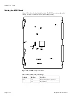
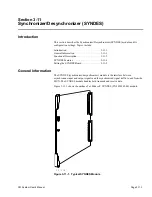
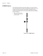

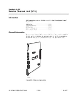
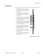


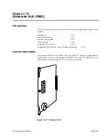


Section 3-13
OWU
Page 3-13-2
CM System User’s Manual
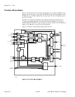
Functional Description
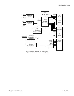
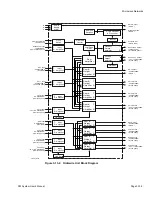
The OWU, when used in with the SCU, provides a full-featured dual-tone multi-
frequency (DTMF) signaling orderwire. It also provides two 4-way/4-wire bridges for
either two 3 kHz channels, intended for VF communications, or one 7 kHz channel to
accommodate split-band type alarm reporting systems, selectable station calling
employing DTMF signaling, and bridging circuits to interconnect multiple radio links at
junctions and repeater sites.
Orderwire service uses VF Channel 1 on the SCU. In a repeater configuration, set VF
Channel 1 on the SCU in through mode to eliminate unnecessary digitized noise from
PCM signal coding and decoding. This through mode is interrupted when the off-hook
situation of the handset is detected.
The OWU works in either a protected or unprotected radio configuration and interfaces
with single or redundant SCU modules. The OWU does not have a redundant
configuration.
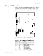
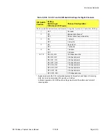
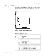
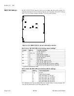
Adjust the levels of VF bridge Channel 13 and 23 with jumper J1 (Table 3-13-A).
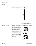
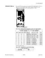
The Orderwire handset connects to the handset Jack of the access panel. When not in use,
the handset hangs from a hook on the right side of the radio.
To make a call using the orderwire handset, set the switch on the handle to TALK. With
the handset keypad, dial the three digit station number you wish to call. Speak into the
microphone in the keypad.
To call all stations at once, press
*
. To terminate a call, press #.
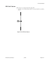
Figure 3-13-2 is a functional block diagram of the OWU.
Содержание CM7
Страница 2: ......
Страница 4: ...Page iv 5 04 05 CM7 8 100Base T System User s Manual ...
Страница 16: ...Glossary Page xvi CM System Users Manual X Y Z ...
Страница 24: ...Microwave Networks CM7 8 100Base T System User s Manual Pagexxiv ...
Страница 62: ...Chapter 2 Operation Page 2 18 5 02 05 CM 100Base T System User s Manual ...
Страница 64: ...Chapter 3 Module Descriptions Page 3 2 CM7 8 100Base T ...
Страница 88: ...Section 3 3 Transmitter Unit Page 3 3 6 CM7 8 System User s Manual ...
Страница 96: ...Section 3 5 RF Power Supply Unit Page 3 5 4 CM System User s Manual ...
Страница 100: ...Section 3 6 SP Power Supply Unit Page 3 6 4 CM System User s Manual ...
Страница 106: ...Section 3 7 Alarm and Control Unit Page 3 7 6 11 18 03 CM 100Base T System User s Manual ...
Страница 124: ...Section 3 11 SYNDES Page 3 11 6 CM System User s Manual ...
Страница 130: ...Section 3 12 SCU Page 3 12 6 11 18 03 CM 100Base T System User s Manual ...
Страница 138: ...Section 3 13 OWU Page 3 13 8 CM System User s Manual ...
Страница 150: ...Section 3 15 NMU Page 3 15 6 CM System User s Manual ...
Страница 192: ...Chapter 5 Verification Page 5 20 CM System User s Manual ...
Страница 194: ...Chapter 6 Maintenance Page 6 2 7 23 03 CM 100Base T System User s Manual ...
Страница 224: ...Chapter 6 Maintenance Page 6 32 7 23 03 CM 100Base T System User s Manual ...
Страница 225: ...CM System User s Manual Page 1 Place any site research or reference material here Site Engineering ...
Страница 226: ...Site Engineering Page 2 CM System User s Manual ...
Страница 230: ...Appendix A T I Curves Page A 4 CM7 8 100Base T System User s Manual ...
Страница 267: ...Microwave Networks CM System User s Manual PageB 37 ...
Страница 268: ...Appendix B QuikLink Page B 38 CM System User s Manual ...
Страница 282: ...Appendix D Alarm Codes Page D 6 5 02 05 CM 100Base T System User s Manual ...
Страница 290: ...Appendix E Setting Frequency Page E 8 CM7 8 System User s Manual ...
Страница 312: ...CM7 8 100Base T System User s Manual Page I 4 Microwave Networks ...


