background image

Appendix B

QuikLink

Page B-28    

CM System Users Manual

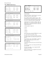
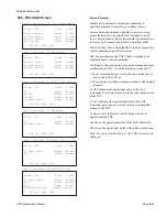
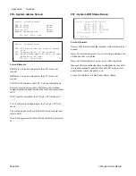
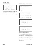
052 - AIS Options Screen

This screen allows you to program the SYNDES Rx to output 
AIS if the BER exceeds 10

-3

. When the AIS feature is 

disabled, the screen displays NO.

Note: For non-protected radios, B side setting is not displayed.

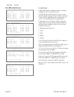
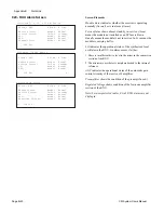
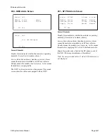
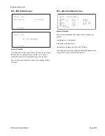
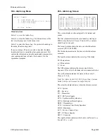
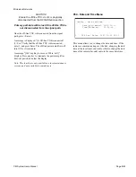
053 -Tx Output Power Calibration Screen

The CM radios do not require calibration.

Follow alignment procedure outlined in Chapter 5, 
Transmitter Output Power and Monitor, to calibrate Tx 
Power Output. Enter the set value into these configuration 
screens.

Note: If a power amplifier is turned off, or APC H is on, the 

display will show no reading, regardless of the configuration.

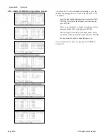
To calibrate the off-line TXU, select item 3, then press Enter. 
A warning message, 

[WARNING: Disconnect Off-line 

TXU First!], 

displays.

L    052 Esc  Enter to change state

 Config - Select AIS Options

 Send AIS when BER > 1e-3?

         A Side       B Side

 --------------------------------------

         >YES          NO

L    053 Esc  Enter Value : 00.0 dBm

 Config - Calibrate Tx Power Output

   Online TXU Output Power: 23.5 dBm

 Config - Calibrate Tx Power Output

     >1. A Side Power    23.5 dBm

      2. B Side Power    21.3 dBm

      3. Calibrate Off-line TXU     A

[                                    ]

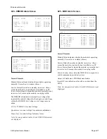
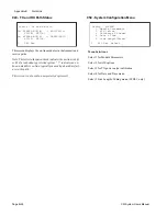
L    053 Esc  Enter Value : 00.0 dBm

 Config - Calibrate Tx Power Output

     >1. A Side Power    23.5 dBm

      2. B Side Power    21.3 dBm

[                                    ]

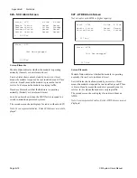
L    053 Esc  Enter Value : 00.0 dBm

 Config - Calibrate Tx Power Output

     Not Applicable

L    053

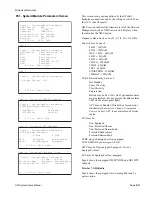
Non-Protected (NN) Configuration

2,6,& 10-GHz HH/HS Configuration (except CM radio)

Hot-Standby (HH) and Space Diversity (HS) Configuration

7/8 GHz (except CM radio)

Freq. Diversity (FF) Configuration (except CM radio)

CM radios

Содержание CM7

Страница 1: ...CM7 8 100Base T Digital Microwave Radio System User s Manual Site____________________ Part Number 8821607 00 Rev E Issued 5 05 ...

Страница 2: ......

Страница 3: ...QuikLink Screens B 27 B 30 Appendix D Alarm Codes All Appendix E Frequency Settings E 1 Appendix F SNMP Option F 3 to F 5 F 7 to F 9 F 12 F 18 Rev C 11 21 03 Front Matter cover revision history TOC Chapter 3 Module Descriptions 3 7 4 3 7 5 3 12 4 3 12 5 Appendix C Configuration Tables C 1 to C 8 Index I 1 to I 4 Rev D 2 25 04 Front Matter all Chapter 3 Module Descriptions 3 1 3 2 3 1 1 to 3 1 12 a...

Страница 4: ...Page iv 5 04 05 CM7 8 100Base T System User s Manual ...

Страница 5: ...ructions on how to use the radio features Chapter 3 Module Descriptions divided into sections with module block diagrams and other module specific information such as operation features and jumper and switch settings Chapter 4 Equipment Installation gives step by step instructions on how to unpack configure and install the radio Chapter 5 System Verification describes radio alignment and tests Cha...

Страница 6: ...oot the radio 6 How to repair the radio 6 How to spare the radio TXU RXU 6 How to switch TX 2 How to switch RX 2 How to initiate loopbacks 2 How to enable or disable APC 2 How to check or change frequency 2 How to change protection configuration 2 How to add service channel 2 How to add orderwire 2 How to add a WTU 2 How to check for alarms 2 How to check the alarm log 2 How to check performance v...

Страница 7: ... warranty shall automatically terminate if the product is used in other than its normal and cus tomary manner has been subject to misuse accident neglect or damage has improper alterations or repairs made to it or if nonconforming parts are used in the product unless done by a service facility authorized by MNI to perform warranty service An authorization to return products to MNI under this warra...

Страница 8: ...eenbriar Stafford TX 77477 USA Tel 281 263 6500 Fax 281 263 6400 Toll free in US 1 888 225 6429 Internet www microwavenetworks com 24 Hour Customer Service Hotline Tel 281 263 6501 Toll free in US 1 888 225 4762 International London Tel 44 1628 788383 Fax 44 1628 788424 ...

Страница 9: ...PC Automatic Power Control ATDE Adaptive Time Domain Equalizer plug in module This unit combats linear channel distortions caused by all sources but is specifically used to fight dispersive fade degradations ATT Attenuation AUX Auxiliary B B8ZS Binary Eight Zero Substitution BB Baseband The lowest frequency around which signals are processed BCH Bose Chaudhuri Hocquenghem A block format FEC code c...

Страница 10: ...in module DFM Dispersive Fade Margin a measure in dB of a system s immunity to dispersive fade activity DISGAP Distributed GAP Dispersive Fade A change in propagation condition which affects the shape of the desired channel response Typically this is caused by multipath activity and is equalized by the ATDE and Slope Equalizer DIU Drop and Insert Unit plug in module DIV Diversity DRO Dielectric Re...

Страница 11: ...de A change in propagation conditions which affects the level of the received signal This is compensated for by receiver AGC and possibly transmitter APC FLC Frame Loss Counter FLS Frame Loss Second Form A Relay with normally open contacts Form B Relay with normally closed contacts Form C Relay with transfer contacts FQ FEC Q Flag FR Frame Resupply FREQ Frequency FS Symbol rate G Gray Code A count...

Страница 12: ...ut ISI Inter symbol Interference J K L LBO Line Build Out LDU Local Display Unit LED Light Emitting Diode LEV Level LNA Low Noise Amplifier LNDC Low Noise Down Converter LO Local Oscillator LOS Line of Site LOW Local Orderwire LPF Low Pass Filter M M M word time or pattern M frame Mbps Megabits per second MDI Media Dependent Interface MGC Manual Gain Control MHSB Monitored Hot Standby radio protec...

Страница 13: ...ally Closed relay contact NCS Network Communications Software NF Noise Figure NM Network Management NMS Network Management System NN Non protected Transmitter Non protected Receiver NO Normally Open relay contact NRZ Non Return to Zero NS Non protected Transmitter Space Diversity Receiver O OC 3 SONET optical line rate of 155 52 Mbps OFS Operational Fixed Services Part 94 O P Output Out of Service...

Страница 14: ...ation QPSK Quadrature Phase Shift Keying Modulation R REA Rural Electrification Administration RF Radio Frequency RFI Radio Frequency Interference RFS Radio Frequency Shelf RMU Rack Mounting Units 1 75 inches RU Rack Unit 1 75 inches RX Receive r RXU Receiver Unit plug in module S SBY Standby SC Service Channel SCU Service Channel Unit plug in module SD Space Diversity radio protection configurati...

Страница 15: ...nchronizer plug in module T T1 Transmission medium capable of carrying a TDM signal at 1 544 Mbps T3 Digital Signal 3 the third multiplex level in North American TDM hierarchy 44 736 Mbps TDM Time Division Multiplexing T I Threshold to Interference TIU TELESCAN Interface Unit T R Transmitter Receiver pair 2 T Rs in a monitored hot standby radio TTL Transistor Transistor Logic TX Transmit ter TXU T...

Страница 16: ...Glossary Page xvi CM System Users Manual X Y Z ...

Страница 17: ...on 2 2 RF Modules 2 3 Branching Waveguide 2 3 Transmitter Unit 2 4 RF Power Supply 2 4 Signal Processing 2 5 Access Panel 2 5 SP Modules 2 5 ATDE and DFM 2 6 RF Equipment Configurations 2 7 Protection 2 7 Protection Switching 2 10 Automatic and Manual 2 10 A Typical SYNDES Module Failure 2 10 Hot Standby Switching 2 10 Transmit Switching 2 11 Transmit SYNDES MUX Switch 2 11 Transmit TXU MOD Switch...

Страница 18: ...Universal 28DS1 to 100BaseT Access Panel 3 1 5 8209245 00 Access Panel 3 1 8 SP Shelf Backplane 3 1 11 Jumpers 3 1 11 RF Shelf Backplane 3 1 12 Equipment Rack 3 1 12 Auxiliary Equipment 3 1 12 Installation Accessory Kit 3 1 12 Section 3 2 RF Distribution General Information 3 2 1 Functional Description 3 2 2 Physical Description 3 2 4 HH Features 3 2 4 HS Features 3 2 5 NS Features 3 2 5 FF Featur...

Страница 19: ...arm and Control Unit ACU Introduction 3 7 1 General Information 3 7 1 Functional Description 3 7 2 ACU Features 3 7 3 Setting the ACU Board 3 7 3 Section 3 8 Modulator MOD Introduction 3 8 1 General Information 3 8 1 Functional Description 3 8 2 MOD Features 3 8 3 Setting the MOD Board 3 8 4 Section 3 9 Demodulator DEMOD Introduction 3 9 1 General Information 3 9 1 Functional Description 3 9 2 DEM...

Страница 20: ...5 Configuring the Orderwire Service Channel and Bridge 3 13 7 Section 3 14 Wayside Traffic Unit WTU Introduction 3 14 1 General Information 3 14 1 Functional Description 3 14 2 WTU User Features 3 14 3 MLN7330 Settings 3 14 4 8000608 00 Settings 3 14 5 MLN7329 Settings 3 14 6 Section 3 15 Network Management Unit NMU Introduction 3 15 1 General Information 3 15 1 Functional Description 3 15 1 Confi...

Страница 21: ...stem Configuration 5 8 SP Operation 5 8 Modulator Frequency 5 9 LO Frequency 5 9 TX Carrier RX LO 5 9 Output Power 5 9 LEDs 5 10 Data Link 5 10 Ethernet Link 5 10 Throughput 5 10 Latency 5 10 Service Channel 5 10 Receive Threshold 5 11 Tx Fade Margin 5 12 Record RSL AGC 5 13 Commissioning the Radio 5 15 Recommended Test Equipment 5 16 Test Tables 5 18 Chapter 6 Maintenance Introduction 6 1 Calling...

Страница 22: ...6 12 Troubleshooting Charts 6 13 Site Engineering Appendix A T I Curves Introduction A 1 T I Ratio A 1 Appendix B QuikLink Screens Introduction B 1 Verifying the ACU Software Version B 1 Software Revision B 1 Screen Layout B 2 Selecting Screens B 2 Aborting Changes B 2 Navigating Screens B 2 Monitoring Radio Functions B 4 Index of Screens B 4 Screen Menu Flowcharts B 7 Local Maintenance Screens B ...

Страница 23: ... Network F 4 Installing Hardware F 5 Connecting Cables F 6 Ethernet 10BaseT Port F 6 SCE Port F 6 Local Access Port F 7 Installing Software F 8 Install F 8 Configure F 8 System Operation F 10 SNMP Network Manager F 10 Microwave Networks MIB F 10 MIB Tables F 10 Performance Table F 11 Configuration Table F 12 Fault Manager Table F 12 CM SNMP Traps F 13 Diagnostics F 13 Telnet F 14 Telnet Commands F...

Страница 24: ...Microwave Networks CM7 8 100Base T System User s Manual Pagexxiv ...

Страница 25: ...BaseT Access Panel 3 1 3 Figure 3 1 3 Power Distribution Diagram 3 1 4 Figure 3 1 4 Features of the Universal 28DS1 to 100BaseT Access Panel 8209302 00 3 1 5 Figure 3 1 5 8209245 00 Access Panel Features 3 1 8 Figure 3 1 6 SNMP Network Interface 3 1 9 Figure 3 1 7 SP Backplane Jumpers from the front of the chassis 3 1 11 Figure 3 1 8 RF Shelf Backplane from the front of the rack 3 1 12 Section 3 2...

Страница 26: ... ACU Features 3 7 3 Section 3 8 Modulator MOD Figure 3 8 1 Modulator 3 8 1 Figure 3 8 2 MOD Block Diagram 3 8 2 Figure 3 8 3 MOD Features 3 8 3 Figure 3 8 4 MOD Board Jumper Locations 3 8 4 Section 3 9 Demodulator DEMOD Figure 3 9 1 Typical Demodulator 3 9 1 Figure 3 9 2 DEMOD Block Diagram 3 9 2 Figure 3 9 3 DEMOD Features 3 9 3 Figure 3 9 4 DEMOD Board Jumper Locations 3 9 4 Section 3 10 Multipl...

Страница 27: ...DIP Switch S1 Values 3 15 5 Chapter 4 Equipment Installation Figure 4 1 Typical 19 Inch Telco Rack 4 2 Figure 4 2 Floor Mounting 4 3 Figure 4 3 Overhead Rack Support 4 3 Figure 4 4 DC Power Connections 4 5 Figure 4 5 Power Connection for Dual Battery Source 4 5 Figure 4 6 Power Connection for a Single Battery Source 4 6 Figure 4 7 Rack Ground Wiring 4 6 Figure 4 8 Improper Ground Connection 4 7 Fi...

Страница 28: ...owchart Performance Monitoring Screens B 7 Figure B 4 Flowchart Alarm and Status Screens B 8 Figure B 5 Flowchart Configuration Screens B 8 Figure B 6 Flowchart Control and Maintenance Screens B 9 Appendix C Configuration Tables Appendix D Alarm Codes Appendix E Setting Frequency Switches Figure E 1 Frequency Switch Arrangement E 2 Figure E 2 CM8 Synthesizer Switch Arrangement E 6 Appendix F CM SN...

Страница 29: ...5 00 DS3 Configuration 3 1 8 Table 3 1 D Jumpers Network Bridge Interface 3 1 8 Table 3 1 E Radio Fuses 3 1 9 Table 3 1 F SP Backplane Jumper Settings 3 1 11 Table 3 1 G MLN7730 Accessory Kit Contents 3 1 12 Section 3 2 RF Distribution Table 3 2 A Waveguide Branching Network Options 3 2 1 Table 3 2 B Transmit and Receive Bandpass Filter Options 3 2 1 Section 3 3 Transmitter Unit TXU Table 3 3 A TX...

Страница 30: ...gs 3 14 4 Table 3 14 C 8000608 00 WTU Equalizer Control Line Length Settings 3 14 5 Table 3 14 D 8000608 00 Line Code Select Settings 3 14 5 Table 3 14 E MLN7329 WTU Jumper Settings 3 14 6 Table 3 14 F MLN7329 WTU Switch Settings 3 14 6 Section 3 15 Network Management Unit NMU Table 3 15 A NMU Jumper Settings 3 15 4 Table 3 15 B NMU Switch S1 Settings 3 15 5 Table 3 15 C NMU Switch S2 Settings 3 1...

Страница 31: ...les Table C A 8209302 00 Configuration Switch Settings C 2 Table C B 8209245 00 Access Panel Settings C 2 Table C C SP Backplane Jumper Settings C 2 Table C D TXU Control Board MLN7973 Jumper Settings C 3 Table C E TXU Control Board MLN7974 Jumper Settings C 3 Table C F RXU Control Board MLN7905 Jumper Settings C 3 Table C G ACU Jumper Settings C 3 Table C H ACU DIP Switch Settings C 4 Table C I M...

Страница 32: ...pendix F CM SNMP Table F A SNMP Components F 2 Table F B Component Descriptions and Part Numbers F 2 Table F C Front Panel Network Interface Components F 2 Table F D SNMP NMU LED Descriptions F 4 Table F E SNMP NMU Push button Reset Switch Descriptions F 4 Table F F SNMP NMU Jumper Descriptions F 4 Table F G Ethernet Port Pins F 6 Table F H SCE Cable Pin Assignments F 7 Table F I Local Access Port...

Страница 33: ... at DS3 45Mbps or E3 34Mbps in a 30 MHz bandwidth The radio transmits and receives signals at frequencies from 7 125 to 8 5 GHz Figure 1 1 shows the typical rack mounted radio Topics in this chapter include Introduction 1 1 Radio Features 1 2 IP Protocol and DS3 E3 Data Transfer 1 3 Radio Network Configuration 1 4 Channel Capacity 1 6 Equipment Description 1 6 Transmission Engineering 1 8 Specific...

Страница 34: ...r radio features of the design include Quadrature Amplitude Modulation 128 QAM modulation scheme that improves spectral perfor mance and meets CTIA requirements for spectral efficiency Forward Error Correction FEC provides error correction for traffic channels and service channels Errorless Space Diversity Switch hitless receiver switching may be used as part of a protection configuration Reverse ...

Страница 35: ...network traffic The SYNDES also accepts TDM data from front panel BNC connectors The SYNDES multiplexes IP and TDM data into packets that contain prioritized data with packet headers which specify packet content and network radio destination For data to be transmitted across a hop to another site the multiplexed data is modulated and sent to the radio transmitter and an antenna for RF transmission...

Страница 36: ...t it operates at full bandwidth 100 Mbps full duplex The secondary interfaces use any instantaneous bandwidth that the primary path does not use In NON PRIORITY mode data interfaces receive equal priority each using half the bandwidth when both operate at high data rates In any priority mode when one data path has minimal or no traffic the other interfaces use the unused bandwidth Figure 1 4 shows...

Страница 37: ... E3 DS3 E3 Site A Site A Site B Figure 1 3 Typical Single Hop Configuration LAN A1 PC LAN B1 PC RADIO 1 UP UP DN DN RADIO 5 UP UP DN DN LAN A2 PC DS3 E3 Site A Site C RADIO 2 UP UP DN DN RADIO 3 UP UP DN DN RADIO 4 UP UP DN DN Site B DS3 E3 RADIO 6 UP UP DN DN LAN B2 PC Site D TX RX DS3 E3 TX RX TX RX TX RX TX RX DS3 E3 Figure 1 4 Multi Hop Configuration ...

Страница 38: ... and individual plug in modules The RF Distribution shelf mounts to the top of the RF shelf RF modules include the Transmitter Unit TXU the Receive Unit RXU and the RF Power Supply Unit RF PSU The SP shelf includes the Access Panel and SP modules for IF signal processing orderwire and alarm and control Remove the radio front cover to access modules before and after installation With the front and ...

Страница 39: ...s Manual 8 12 03 Page1 7 Table 1 B CM7 8 100Base T Radio Sections and Modules Section Module RF Section RF Distribution Transmitter Unit TXU Receiver Unit RXU RF Power Supply Unit RF PSU Figure 1 5 CM7 8 100Base T Radio in Hot Standby Configuration ...

Страница 40: ...her interference immunity than FDM FM receivers Interference in an analog system shows up in the voice channels in direct proportion to the level of the interference relative to the message carrier In a digital radio like the CM7 8 interference only becomes apparent when it is of sufficient level such that the T I ratio of the digital receiver has been violated Appendix A illustrates and defines T...

Страница 41: ... Power and threshold are guaranteed engineering specifications at 25 C as measure at the antenna flange Transmitter Power Table 1 C lists the CM7 8 transmitter rated power output Power is measured at the antenna connection to the radio and no additional branching losses need be added Receiver Sensitivity Tables 1 C outlines minimum threshold receive signal level of the CM7 8 1x1 hot standby receiv...

Страница 42: ...ored Hot Standby Typical System Gain 10 3 BER APC High D High Power DHP 101 5 100 5 High Power HP 98 5 dB Standard Power SP 93 5 dB Modulation Type 128 QAM Transmission Rate 166 77 Mbps Channel Bandwidth 30 MHz Dispersive Fade Margin 10 3 BER 49 0 dB 10 6 BER 47 0 dB Residual BER 10 13 Antenna Waveguide Flange Type CMR112F Required Antenna VSWR Return Loss 1 43 1 15 dB Transmitter Power Output Sta...

Страница 43: ...put Tx Level 3 5 dBm 16 dBm option Output Rx Level 3 5 dBm 7 dBm option Idle Channel Noise narrow band 23 dBrnC Orderwire Optional Frequency 300 3400 Hz Signaling DTMF allows all call group and local Features Talk Switch 4 way 4 wire bridge Wayside Traffic Unit Optional Wayside Traffic Channel 1 Data Rate 19 2 kbps asynchronous Connector RJ 11 Jack Electrical Hot Standby Input Voltage Range 20 to ...

Страница 44: ...he antenna flange Contact Rating 0 5 A 30 Vdc NMU Output Type Std TTL Relay Alarm Outputs Number of Relay Outputs 4 Type Form C Dry Contact NO NC COMM Contact Rating 0 5 A 30 Vdc Operating Environment Ambient Temperature 0 to 50 C 32 to 122 F Humidity 95 no condensation Altitude AMSL 15 000 ft 4 500 m Mechanical Height 33 25 in 845 mm Width 17 25 in 438 mm Depth 10 25 in 260 mm plus 4 1875 106 mm ...

Страница 45: ...en conversion to a radio frequency RF signal Transmit data enters the radio at the front panel and proceeds through the radio modules as follows Synchronizer Desynchronizer SYNDES Module accepts IP data from 100Base T channels that connect to an on board Ethernet switch multiplexes the IP data with incoming DS3 or E3 TDM data and sends non return to zero NRZ data stream to the MUX multiplexer Serv...

Страница 46: ... the DEMOD Internal to the RXU the signal goes through a low noise pre amplification stage and a downconversion process that uses a frequency synthesizer to provide a local oscillator The unit amplifies filters and applies the resultant 70 MHz signal to the DEMOD Demodulator DEMOD receives a multi level QAM signal centered at 70 MHz from the RXU Performs the complementary function to the MOD by re...

Страница 47: ...eguide The waveguide branching network is the interconnection of the RF signal between the antenna and the transmit and receive RF filters Waveguide fastens to the back cover of the radio Table 2 A lists the four branching network configurations available on the CM radio Figures 2 3 to 2 6 provide simplified block diagrams of these RF configurations F 1207 RF IN RXU AGC MON RF LPBK LO FREQ ADJ LPB...

Страница 48: ...r supplies come in the hot standby protection configuration one for the main and one for the redundant radio A single RF PSU comes in the non protected radio When protection is desired for the transmitter or receiver operations it is possible to establish a configuration on the RF shelf of two transmitters main and hot standby transmitters two receivers main and hot standby receivers and two RF po...

Страница 49: ...ls the orderwire and bridge legs 4 position 4 pin modular jack for the WTU DS1 channel DB15 and DB25 connections for connecting external alarm and aux iliary TTL signals through the radio for network management Note This list does not include unused connections See Section 3 1 Radio Cabinet SP Modules The signal processing SP chassis houses modules just below the access panel SP modules convert cu...

Страница 50: ...e direct signal All signals combine at the receive antenna and can cause amplitude and phase distortion of the direct signal Normally this distortion is minimal and easily handled by the receiver because the direct signal is stronger than reflected signals However under fading conditions the direct signal may be attenuated and the distortion increased to the point where frequency selective notches...

Страница 51: ...nnects to the antenna system and the radio is equipped with two of each module one for primary and one for standby Figure 2 3 illustrates signal flow in this configuration 2 Hot Standby Transmitter Space Diversity Receiver HS This configuration is similar to the Hot Standby Transmitter Hot Standby Receiver except for the addition of a second antenna port for the B Receiver and the ability to perfo...

Страница 52: ...nsmitter Non protected Receiver NN This protection config uration offers no redundancy in the RF Unit Figure 2 6 illustrates signal flow in this configuration From MOD A To DEMOD A F 1133 TX A RX A RX B RF Dist Filter RF Dist Filter TX B LO LO SYNTHESIZER SYNTHESIZER RF Dist Filter Antenna Port Antenna Port From MOD B To DEMOD B 20 to 60 VDC Power Supply A To TX A RX A 20 to 60 VDC Power Supply B ...

Страница 53: ...r LO SYNTHESIZER SYNTHESIZER To DEMOD B 20 to 60 VDC Power Supply A To TX A RX A 20 to 60 VDC Power Supply B To TX B RX B Figure 2 5 Non Protected TX Space Diversity RX NS 20 to 60 VDC Power Supply A To TX A RX A To DEMOD A From MOD A F 1132b TX A RX A Antenna Port RF Dist Filter RF Dist Filter LO SYNTHESIZER Figure 2 6 Non Protected TX RX NN Signal Flow ...

Страница 54: ...s the on line status of the radio As a shortcut for displaying Screen 040 the user may from any screen simply enter 040 and press Enter In modules that handle transmit and receive functions such as the SYNDES SCU WTU and MUX only that portion of the module that fails switches A failure in the transmit portion of one of these modules causes a transmit switch leaving the receive section in its curre...

Страница 55: ...t TXU MOD Switch The second switch level on the transmit side is the TXU MOD switch The output from the main MOD goes to the input of the main TXU Similarly the output of the redundant MOD goes to the input of the redundant TXU After conversion and amplification in the TXU the TXU MOD switch sets the online TXU MOD and the TXU switch together If the main MOD fails the redundant MOD and TXU switch ...

Страница 56: ...SCU or WTU 4 Select one of the options below and then press Enter a switch paths automatically b switch radio A on line c switch radio B on line d lock the current selection on line Receive Switching The receive side of the radio also has four switching levels as Figure 2 7 illustrates RXU DEMOD SYNDES MUX SCU WTU Receiver RXU DEMOD Switch The received signal is split and applied to both RXUs The ...

Страница 57: ...s without impacting the primary traffic on the radio In the event of a failure in the A radio SCU B radio SCU is placed online Receive WTU Switch The fourth receiver switch is the WTU switch This switch level is valid only when protected WTUs are equipped This level is provided to allow switching of the protected WTUs without impacting the primary traffic on the radio In the event of a failure in ...

Страница 58: ... LAN B DS3 E3 SCU Local Loopback WTU Local Loopback MUX Local Loopback IF Local Loopback not supported on radios with 3DS3 or greater capacity RF Local Loopback SYNDES Remote Loopback SCU Remote Loopback WTU Remote Loopback T XA R XA R XB T XB S C UA T x R x S Y N D E SA S Y N D E SB R x T x M U XA M U XB LA NA S e rviceC ha n ne l R x T x R x T x R x T x D E M O D B M O DA D E M O D A R x T x F 1...

Страница 59: ... the LED blinks at both local and remote radios Performing RF Local Loopback RF local loopback isolates waveguide antenna feed or path related problems RF loopback ensures that a terminal works from the data input to the RF waveguide filters RF Loopback Note RF local loopback stops traffic on the path under test On protected systems per form RF Local Loopback on the off line radio Use the followin...

Страница 60: ...ck to test the digital or analog service channels The MUX must be installed the SP shelf to set SCU local loopback SCU remote loopback tests far end and local radio SCU MUX MOD DEMOD and RF sections for problems without interrupting data The SCU to be tested must be in service online and the remote SCU transmit and receive paths must be on the same unit The VF receive output signal is about 3 dB h...

Страница 61: ...ly control automatically by the ACU A bit error rate BER worse than 10 11 and a receive signal level RSL within 15dB of the specified threshold cause the ACU to turn APC on This prevents APC from coming on during module failures or selective fading After the fade condition the ACU returns APC to low Enable APC on the ACU using switch SW3 position 8 To manually activate APC follow these steps from ...

Страница 62: ...Chapter 2 Operation Page 2 18 5 02 05 CM 100Base T System User s Manual ...

Страница 63: ...L853A 8GHz Transmitter Unit TXU High Pwr MTL851A 7GHz MTL854A 8GHz Transmitter Unit TXN DHP Pwr MTL852A 7GHz MTL855A 8GHz 3 4 Receiver Unit RXU Band 7 1 MRL8166A Receiver Unit RXU Band 7 2 MRL8167A Receiver Unit RXU Band 7 3 MRL8168A 3 5 Radio Frequency Power Supply Unit RF PSU MPN8187 3 6 Signal Processing Power Supply Unit SP PSU MPN6050 3 7 Alarm and Control Unit ACU MLN7195 ACU Software MVN402...

Страница 64: ...Chapter 3 Module Descriptions Page 3 2 CM7 8 100Base T ...

Страница 65: ...ry installs the network management and 100BaseT ethernet or optical interfaces when purchased The early model common access panel P N 8209245 00 01 was used on 12DS1 3DS3 155Mbps and 100BaseT radios The panel contains operator controls status indicators power fuses port for local radio maintenance interfaces for electrical or optical line signals connections to service channels orderwire and waysi...

Страница 66: ...Section 3 1 Chassis Page 3 1 2 CM System User s Manual Figure 3 1 1 8209309 00 Universal 28DS1 3DS3 155 Mbps and 100BaseT Access Panel ...

Страница 67: ...Microwave Networks CM System User s Manual Page3 1 3 Figure 3 1 2 8209245 00 Common 12DS1 3DS3 155 Mbps and 100BaseT Access Panel ...

Страница 68: ...ormance and status data and helps configure the radio and initiate diagnostics A Local Maintenance Terminal LMT connects to the Local Access port to operate the QuikLink application see Chapter 4 Installation Connecting Performance Monitoring Devices QuikLink also provides access to an event log and up to seven days of performance statistics Statistics include Bit Error Rate BER Errored Seconds ES...

Страница 69: ... Kit 8708262 01 100BaseT Kit Non Protected 8708262 02 100BaseT Kit Protected 8708262 03 Access Panel Accessory Kit 8708220 xx Figure 3 1 4 calls out each indicator control and connector on the access panel Text below describes each item See Chapter 4 Installation for connector pinning 1 DS1 Connectors J21 J22 J23 50 pin TELCO connectors for 100 Ω balanced DS1 line signals J23 Includes wayside chan...

Страница 70: ...ns Channels accommodate 150 bps to 19 2 kbps asynchronous data at RS232 levels SCU configuration jumpers set the data rate 8 SCE Jack Modular jack for Status and Control Extender SCE connection The SCE extends Alarm Control relays to provide system alarm status and performance infor mation to and controls from remote equipment See the SCE Operation Manual order P N 6885104E05 9 TTL I O DB15 for TT...

Страница 71: ... duplex connection for 155 Mbit optical data 19 LAN A B Connectors RJ45 jacks for up link MDI and down link MDI X Ether net connection Table 3 1 A 8209302 00 Configuration Switch Settings SWITCH 1DS3 3DS3 28DS1 100BaseT 1DS3 SONET Electrical SONET Optical S3 1 OFF OFF OFF OFF ON OFF S3 2 OFF ON OFF OFF OFF OFF S3 3 OFF OFF OFF OFF ON OFF S3 4 OFF OFF OFF OFF ON OFF S3 5 OFF ON OFF OFF OFF OFF S3 6...

Страница 72: ... Table 3 1 C set DS3 configu ration 3 Network Jacks One of two options P4 or SNMP For P4 Network Two modular jacks that connect proprietary network management data between co located radios and to the Telescan network management system Uni or omni directional configuration requires an associated Network Management Unit Section 3 15 and appropriate jumper settings on the Network Bridge Interface to...

Страница 73: ...ion to and controls from remote equipment See the SCE Operation Manual order P N 6885104E05 9 TTL I O DB15 for TTL input and output to the NMU 10 Alarm Control Relay DB25 connector to system alarm status and performance in formation to and controls from remote alarm monitoring equipment 11 SPKR Jack Four position four pin modular jack for an external speaker 12 DTE DCE Switch In DCE Local Access p...

Страница 74: ...ocal on site mainte nance configuration and monitoring 14 WTU Jack WTU channel 1 connector 15 HANDSET Jack Modular telephone jack for the orderwire handset 16 SYNDES Connector SYNDES connections on DS1 radios 17 SYNDES Connector SYNDES connections on 3DS3 and SONET electrical radios 18 OC3 In Out Connectors SC type duplex connection for 155 Mbit optical data 19 LAN A B Connectors RJ45 jacks for up...

Страница 75: ... the chassis behind the main SPPSU Figure 3 1 7 To reach the jumpers remove the A SPPSU from the chassis Table 3 1 F SP Backplane Jumper Settings Set E1 and only one of the capacity jumpers Jumper Setting Function Enabled E1 Strapped Normal operation E4 Strapped 4DS1 4DS1N operation E5 Strapped 8DS1 operation E6 Strapped 12DS1 8DS1N operation E7 Strapped 28DS1 3DS3 155Mbps 100Base T operation E2 E...

Страница 76: ...units apart When adding a fuse panel install it one rack unit above the radio cabinet The fuse panel is the only auxiliary equipment mounted above a rack Installation Accessory Kit Table 3 1 G lists the contents of the installation kit packed with the radio Table 3 1 G MLN7730 Accessory Kit Contents ITEM P N QTY Static Control Wrist Strap 6684760P01 1 Accessory Installation Tuning Tool 6685389E36 ...

Страница 77: ...ailable configurations of the branching network Table 3 2 B lists available frequency bands of the transmit and receive bandpass waveguide filters Table 3 2 A Waveguide Branching Network Options Part Number Version MLL8177A Transmit Hot Standby Receive Hot Standby HH MLL8178A Transmit Hot Standby Receive Space Diversity HS Transmit Non protected Receive Space Diversity NS MLL8180A Transmit Frequen...

Страница 78: ... a transmit filter and the received signal from the antenna goes from the Rx filter through coax to the receiver In hot standby transmit space diversity receive HS configurations waveguide routes signals from both transmitters and primary receiver to and from a common antenna A secondary receiver connects to the diversity antenna as Figure 3 2 2 shows TX A RX A F 1135 To From Antenna TX B RX B ON ...

Страница 79: ...re 3 2 3 shows In the frequency diversity transmit and receiver FF configuration waveguide routes RF signals from the primary and diversity transmitters and receivers to and from a common antenna through circulators as Figure 3 2 4 shows TX A RX A F 1134B From Space Diversity Antenna To From Antenna RX B ON LINE M ON Figure 3 2 3 NS TX Non Protected RX Space Diversity RF Distribution TX A RX A ffb...

Страница 80: ...feeds the signal from TX A to the branching network 2 RF IN Transmit filter input that feeds the signal from TX B to the branching network 3 RF OUT Receive filter output that sends the signal to RX A 4 RF OUT Receive filter output that sends the signal to RX B This signal is 10 dB low er than that sent to RX A 5 ONLINE MON coupled transmit signal used to set the online transmitter power level NOTE...

Страница 81: ...B 5 ONLINE MON coupled transmit signal to set the online transmitter power level NS Features Figure 3 2 8 shows components of the non protected TX space diversity Rx NS branching network that the following text describes 1 RF IN Transmit filter input that feeds the signal from TX A to the branching network 2 ONLINE MON coupled transmit signal used to set the online transmitter power level 3 RF OUT...

Страница 82: ...ends the signal to RX B 5 ONLINE MON coupled transmit signal used to set the online transmitter power level 6 ONLINE MON coupled transmit signal used to set the online transmitter power level NN Features Refer to Figure 3 2 10 for the locations of the following components for the Non protected Non protected version of the branching network 1 RF IN Transmit filter input that feeds the signal from T...

Страница 83: ...resides in the RF shelf of the radio Figure 3 3 1 shows the TXU Table 3 3 A lists the TXU part numbers for both the installed and spare units Spares ship without conversion filters see Chapter 6 Replacing Modules The x in the TXU part number varies with the Tx Rx spacing option as set by the TX IF BPF LO board See Table 3 3 B Table 3 3 A TXU Part Numbers Part Number installed spare Output Power Tx...

Страница 84: ...The resultant RF signal is further amplified and sent to the output Figure 3 3 2 shows a functional block diagram of the Transmitter Unit Table 3 3 B Tx Rx Spacing Options X in TXU P N T R Spacing MHz 0 119 126 1 150 151 614 154 160 161 2 175 182 3 196 4 245 5 300 6 168 F 1137 To Switch TX Alarm RF OUT MUX Out BPF TX Power Adjust Switch Confirm APC IF In IF Loopback LO LO Input from RXU PLL Alarm ...

Страница 85: ...SMA interface that receives the LO signal from the synthesizer on the adjacent RXU through a 141 semi rigid coaxial cable 4 TX ALM Red LED that indi cates the TXU is in alarm Con trolled by the ACU 5 TX PWR ADJ Potentiometer that adjusts the TXU power level 6 IF IN SMA interface that re ceives the 70 MHz IF signal from the MOD 7 LPBK LO OUT SMA interface for test and measurement Con nects the firs...

Страница 86: ...put power configuration from a circuit in the power amplifier TX IF BPF LO The IF BPF LO board has up to three configurable jumpers and two jumpers for factory test Figure 3 3 5 shows the jumper locations and Table 3 3 C lists the Tx Rx frequency spacing options board part numbers and jumper settings Settings not listed indicate that the jumper is not on the board Figure 3 3 4 TXU Alarm Control Bo...

Страница 87: ...N8110 MLN8210 1 2 1 2 1 2 CM8 151 614 MHz MLN8110 MLN8210 1 2 1 2 2 3 CM7 154 MHz MLN8110 MLN8210 1 2 2 3 2 3 CM7 160 MHz MLN8110 MLN8210 2 3 1 2 1 2 CM7 161 MHz MLN8110 MLN8210 2 3 1 2 2 3 CM7 168 MHz MLN8108 MLN8209 1 2 CM7 175 MHz MLN8108 MLN8208 1 2 1 2 CM7 8 182 MHz MLN8108 MLN8208 2 3 2 3 CM7 196 MHz MLN8107 MLN8207 1 2 CM7 8 245 MHz MLN8106 MLN8206 1 2 1 2 CM8 266 MHz MLN8106 MLN8206 2 3 2 ...

Страница 88: ...Section 3 3 Transmitter Unit Page 3 3 6 CM7 8 System User s Manual ...

Страница 89: ...anel Features 3 4 3 Setting RX Boards 3 4 4 General Information The Receiver Unit RXU accepts an input signal at the Rx frequency and converts it to an intermediate frequency IF signal Figure 3 4 1 shows the RXU Table 3 4 A lists RXU part numbers The RXU has two frequency setting switches S1 and S2 Appendix E Frequency Switch Settings describes how to change the operating frequency of your radio F...

Страница 90: ...nd Rx LO Frequency GHz Synthesizer Part Number CM7 CM8 CM7 CM8 CM7 CM8 CM7 CM8 MRL8166A MRL8170A 7 1 8 1 7 030 7 235 7 850 8 030 MLL8156A MLL8160A MRL8167A MRL8171A 7 2 8 2 7 235 7 440 8 030 8 210 MLL8157A MLL8161A MRL8168A MRL8172A 7 3 8 3 7 440 7 645 8 210 8 390 MLL8158A MLL8162A MRL8169A MRL8173A 7 4 8 4 7 645 7 850 8 390 8 570 MLL8159A MLL8163A RF Loopback LO F 1138 RX Alarm LO Alarm MAN RSL S...

Страница 91: ...he DE MOD 5 LPBK LO IN SMA connector that re ceives the first conversion LO signal from the adjacent TXU for RF local loop back test 6 AGC MON Test point for AGC voltage RSL 7 RX ALM Red LED controlled by the ACU that indicates the RXU is in alarm 8 GND Test point ground connection 9 LO MON SMA interface that is a sam ple of the LO signal for monitoring The signal level is 5 dBm The LO frequency i...

Страница 92: ...Board MLN7905A Jumper Settings Jumper Setting Label Function E1 1 2 RF LO 2 3 RF LO Sideband Option Sets for upper or lower side band Depends on bandwidth option E2 2 3 AUTO MAN AUTO Factory test and adjustment E3 E4 2 3 1DS1 DS3 10 MHz 1 2 3DS3 30 MHz Bandwidth Option Sets appropriate channel bandwidth for system capac ity 3 3DS3 E3 1 MDS1 DS3 RF LO E1 F 1250 AUTO 1 E2 MAN DS1 S1 LBCK LBCK LO IN ...

Страница 93: ...ude Introduction 3 5 1 General Information 3 5 1 Functional Description 3 5 2 RF PSU Board Features 3 5 3 General Information The RF PSU P N MPN8187A is a two output 156 watt supply that converts battery power into regulated voltages to power the RF units Figure 3 5 1 shows the power supply r f p s u Figure 3 5 1 RF Power Supply Unit Section 3 5 RF Power Supply Unit RF PSU ...

Страница 94: ...single unit can accept either positive or negative primary voltage from 20 to 60 Vdc or 20 to 60 Vdc Figure 3 5 2 is a functional block diagram of the RF PSU Figure 3 5 2 RF PSU Block Diagram 3 Filter Filter 8 Filter Filter DC DC Converter ACU Interface P S Alarm Input BAT BAT Test Point Input BAT BAT T est Point Alarm Control From ACU Monitored Signals Control Signals 12 3 VDC 12 3 VDC Test Point...

Страница 95: ...oints from the front panel The following text describes these features 1 ALM LED Indicates the RF Power Supply is in alarm ACU controls this red alarm LED 2 GND Test Point Ground connection for all test points on the RF PSU 3 12 3 V Test Point Voltage test point 4 6 V Test Point Voltage test point 5 BATT Positive battery test point 6 BATT Negative test point Figure 3 5 3 RF Power Supply Board ...

Страница 96: ...Section 3 5 RF Power Supply Unit Page 3 5 4 CM System User s Manual ...

Страница 97: ...Description 3 6 2 SP Power Supply Features 3 6 3 General Information The Signal Processing Power Supply Unit SP PSU converts battery voltage into regulated outputs that supply power to the SP shelf of the radio The SP PSU part number MPN6050 sits in the radio SP shelf Figure 3 6 1 shows the SP PSU F 0 7 7 7 0 Figure 3 6 1 SP Power Supply Unit Section 3 6 SP Power Supply Unit SP PSU ...

Страница 98: ...y voltage from 20 to 60 Vdc or 20 to 60 Vdc For proper operation each output voltage must have a minimum of 25 of maximum load Figure 3 6 2 shows a block diagram of the SP PSU 3 3 Window Comparator 3 Alarm GND 5 4V 6V 6V DC DC Converter Input Filter BAT In BAT In Out to ACU 3 10 ACU Interface MUX From ACU Output Filter Output Filter Output Filter 6V Test Point 6V Test Point 5 4V Test Point GND Tes...

Страница 99: ...d indicators controls and test points 1 ALM Red LED controlled by the ACU that indicates the SP Power Supply is in alarm May be fuse or internal failure 2 GND Ground for voltage test points 3 5 4 V Voltage test point 4 6 0 V Voltage test point 5 6 0 V Voltage test point 6 BAT Positive battery voltage 7 BAT Negative battery voltage Figure 3 6 3 SP PSU Features ...

Страница 100: ...Section 3 6 SP Power Supply Unit Page 3 6 4 CM System User s Manual ...

Страница 101: ...General Information The Alarm and Control Unit ACU Figure 3 7 1 supervises radio operation The ACU processor and system software collects alarm and status information from radio modules Based on collected data the ACU sets alarms and switches to redundant units where appropriate The ACU also maintains an alarm log and history of radio performance F 0 3 2 7 r 0 4 9 4 O p t i o n a l N M U Figure 3 ...

Страница 102: ...o light its alarm LED The alarm condition may also cause the ACU to initiate a path protection switch Counters in the ACU monitor FEC and parity error signals from the MUX to determine when to start adaptive power control perform a path protection switch and to calculate the bit error rate The ACU maintains a 512 event history called the Alarm Log and a seven day performance log of the radio perfo...

Страница 103: ...e ACU Board The ACU has six jumpers and four switches two push switches and two DIP switches Figure 3 7 4 shows jumper and switch location and Table 3 7 A lists ACU configuration settings Table 3 7 B lists switch settings for switches S2 and S3 which are radio configuration settings Switch S1 is for factory test only Push switch S4 resets the system software CAUTION Reset pressing switch S4 replac...

Страница 104: ...tion Enabled E1 E2 E3 1 2 Normal operation 2 3 Factory test E4 1 2 Alarm Cut Off ACO disables audible and visual alarm 2 3 ACO only disables audible alarm E5 1 2 ACU fail causes minor alarm only 2 3 ACU fail causes major and minor alarm E6 1 2 4 Port NMU see NMU section for details 2 3 Normal NMU Figure 3 7 4 ACU Jumper and Switch Locations ...

Страница 105: ... Disabled APC ON at Power Up Mode Enable 8 Closed Status and Control Extender not equipped Open Status and Control Extender equipped S3 1 2 3 Closed Closed Closed TX Hot Standby RX Hot Standby Closed Closed Open TX Hot Standby RX Space Diversity Closed Open Closed TX Space Diversity RX Space Diversity Closed Open Open TX Non protected RX Non protected Open Closed Closed TX Non protected RX Space D...

Страница 106: ...Section 3 7 Alarm and Control Unit Page 3 7 6 11 18 03 CM 100Base T System User s Manual ...

Страница 107: ...on 3 8 1 General Information 3 8 1 Functional Description 3 8 2 MOD Features 3 8 3 Setting the MOD Board 3 8 4 General Information A module in the SP shelf the Modulator MOD generates the modulated IF signal The MOD is specific to radio capacity part number 8000514 00 for the 155 Mbps radio Figure 3 8 1 Modulator Section 3 8 Modulator MOD ...

Страница 108: ...ar EYE pattern these signals should be sent through the root raised cosine filter on the DEMOD Figure 3 8 2 shows the MOD block diagram F 2701 A B S elect M U X A C U S elect I FromM U XA C lk P LL QD ata I Data D ata C lk TX B aseband Filter D igital Filter IFO utput Buffer 70 M H zoutpu toR FShelf M onitored S ignals 6V 6V A C U Interface Control S ignals 5VReg clk Q clk I Q clk FromM UXB T o Fm...

Страница 109: ...s in an alarm condition Controlled by the ACU 3 I BB OUT E2 75 ohm test connector for analog baseband 2 position header 4 Q BB OUT E3 75 ohm test connector for analog baseband 2 position header Note I and Q baseband outputs are root raised co sine signals To get a clear EYE pattern send the signals through the root raised cosine fil ter on the DEMOD 5 CLK OUT E5 Test connector Clock used with anal...

Страница 110: ...8 4 shows these jumpers and Table 3 8 B lists factory default jumper settings E2 E3 and E5 are 2 position header connectors for factory test Table 3 8 A MOD Jumper Settings Jumper Setting Function Enabled E1 E6 E8 Open For factory tests E7 Installed Connects Q DAC to baseband filter E9 Installed Connects I DAC to baseband filter Figure 3 8 4 MOD Board Jumper Locations ...

Страница 111: ...MOD Board 3 9 4 General Information A module in the SP shelf the DEMOD Figure 3 9 1 remove the 70 MHz modulation from the receive signal and passes data and clock onto the demultiplexer for further signal conditioning Set the SP backplane for the DEMOD operation at 128 QAM The DEMOD for a 155 Mbps radio part number 8000515 00 may look slightly different than Figure 3 9 1 shows F 0 8 5 5 a Figure 3...

Страница 112: ...demapping and decision directed loops of the ATDE output The ATDE provides higher order signal compensation The FPGA extracts symbol clock timing from the equalized I and Q signals A differential signal from the FPGA drives a VCXO The demapped I and Q data streams go to the MUX for conversion back to error corrected data and overhead Analog control loops provide I and Q coarse AGC and slope equali...

Страница 113: ...nd associated ground 2 ALM Red LED controlled by the ACU that indicates the DEMOD is in alarm due to an internal fault or a fault in the RXU or MUX 3 CLK Symbol rate clock test point used to synchronize eye pattern moni toring 50 ohms and ground associat ed with CLK test point 4 MCX Connector IF input from the RXU 50 ohms 5 Q EYE Q axis eye pattern test point 50 ohms and associated ground Figure 3...

Страница 114: ...P3 I FINE OFFSET Factory test only OFF JP4 I FINE GAIN Factory test only OFF JP5 70 MHZ VCO TUNE Factory test only OFF JP6 QUAD CONTROL Factory test only OFF JP8 EXTERNAL 70 MHz VCO Factory test only 2 3 JP9 I SLOPE EQ DISABLE Factory test only OFF JP11 EXTERNAL B B INPUT Factory test only OFF JP12 I B B INPUT Factory test connection OFF S1 3 ADTE DISABLE Factory test only OFF JP21 Q B B INPUT Fac...

Страница 115: ...ion The multiplexer MUX combines several signals into a composite data stream for transmission and in the receive direction demultiplexes the data stream into its original signals The MUX module Figure 3 10 1 resides in the SP shelf The 155 Mbps radio uses one of two module variations one for use with an optional DS1 wayside channel P N 8000513 00 and one for use with an optional E1 wayside channe...

Страница 116: ... and clock signals which it sends to the SYNDES Figure 3 10 2 shows a MUX functional block diagram From Service Channel SC SD Elastic Buffer CH1 CH4 From SYNDES Gap Buffer To Modulator A To From ACU Bit Multiplexer Scram bler FEC TD Frame Generator ACU Interface Bit Demultiplexer RC De scrambler FEC CKT Framer DT Phase Resolve Phase Resolve From Demodulator A From Demodulator B To Service Channel ...

Страница 117: ...ows the MUX as seen from the front of the radio The call out shows the location of the front panel ALM LED 1 ALM Red LED controlled by the ACU that shows when the MUX is in an alarm condition The alarm may be due to a MUX fault or a SYNDES MOD or DEMOD fault Figure 3 10 3 MUX Features ...

Страница 118: ... 10 4 shows the board jumper locations The MUX has no user configuration settings so Table 3 10 B lists the factory default jumper setting Table 3 10 A MUX Jumper Settings Jumper Setting Function JP4 1 2 FEC Enabled normal operation 2 3 FEC Disabled Figure 3 10 4 MUX Jumper Locations ...

Страница 119: ...es 3 11 4 Setting the SYNDES Board 3 11 5 General Information The SYNDES synchronizer desynchronizer module is the interface between asynchronous input and output signals and the synchronized signal traffic to and from the MUX The SYNDES module handles both transmit and receive data Figure 3 11 1 shows the outline of a 100base T SYNDES PN 8050542 00 module F 0 1 2 5 B Figure 3 11 1 Typical SYNDES ...

Страница 120: ...s on whether the data stream includes a DS3 or E3 channel Priority settings Chapter 4 Paragraph 4 0 commit bandwidth to each port The SYNDES recovers data and clock from the DS3 or E3 input data stream and sends this directly to the MUX interface at 44 736 MHz DS3 or 34 368 MHz E3 In all cases data travels as frames to the MUX interface at 155 52 Mbps via a 4 bit interface Data frames include bits...

Страница 121: ...3 E3 Transmit Receive MUX Clock Recovery FIFO Half Full Reduce Jitter Up Dn Ethernet Switch Up Dn Rx Nibble From MUX Tx Nibble To MUX ACU Nibble Osc 38 88 MHz Data Clk DS3 E3 Data Clk Priority Mode Select IP Data TDM ACU Control and Status Figure 3 11 2 SYNDES Block Diagram ...

Страница 122: ...alarm would be when the alarm indication circuit detects the absence of clock data when transmitting The alarm indication blue signal AIS generator sends an all ones signal upstream which alerts upstream equipment and the ACU The ACU initiates an alarm and the alarm LED lights to signal the condition 1 ALM Red LED indicates the SYNDES is in alarm The ACU controls this LED Figure 3 11 3 SYNDES Feat...

Страница 123: ...face Switch S1 is used during factory programming All positions of S1 must remain OFF for during operation Table 3 11 A S2 10 100Base T Interface Mode Setting Switch Position Mode Pos 1 On LAN A priority Off No priority Pos 2 On TDM DS3 E3 Channel present Off No TDM Channel Pos 3 On DS3 on TDM Channel Off E3 on TDM channel Pos 4 On DS3 E3 channel equipped Closed DS3 E3 channel non equipped Data I ...

Страница 124: ...Section 3 11 SYNDES Page 3 11 6 CM System User s Manual ...

Страница 125: ...tion 3 12 1 SCU Features 3 12 3 Setting the SCU Board 3 12 4 General Information The Service Channel Unit SCU provides two VF channels that operate from 300 Hz to 3400 Hz and two 19 2 kbps data channels using an RS232C RS423 electrical interface The MLN7876 SCU shown in Figure 3 12 1 resides in the SP shelf of the radio F 1240 Figure 3 12 1 Service Channel Unit Section 3 12 Service Channel Unit SC...

Страница 126: ...nchronous data each The interface to the data channels is a three wire TX RX GND RS232C RS423 type connection at the Access Panel See the Installation chapter of this manual for connector and pin designations Figure 3 12 2 shows a functional block diagram of the SCU On Line Relay On Line Relay Switch Control 3 State Drivers HS PLL PCM CODEC Pass Thru PCM CODEC Pass Thru 4 MUX 4 DE MUX ACU Interfac...

Страница 127: ... for output Channel 1 signal level Set by placing a 3 5 dBm 1 kHz sine wave input and adjust ing to 3 5 dBm output gain 4 CH2 OUTPUT GAIN Factory set point for output Channel 2 signal level Set by placing a 3 5 dBm 1kHz sine wave input and adjust ing to 3 5 dBm output gain 5 ALM Red LED that indicates the SCU is in alarm The alarm may be caused by internal fault or a failure of the MUX The alarm i...

Страница 128: ... S2 Table 3 12 A SCU Jumper Settings Jumper Setting Function Enabled J1 1 2 High gain 23 dB on VF Channel 2 16 dBm input 7 dBm output 2 3 Low gain 0 dB on VF Channel 2 3 5 dBm input 3 5 dBm output J2 1 2 High gain 23 dB on VF Channel 1 16 dBm input 7 dBm output 2 3 Low gain 0 dB on VF Channel 1 3 5 dBm input 3 5 dBm output J4 1 2 Oscillator test 2 3 Oscillator enabled For Dip Switch settings see T...

Страница 129: ...tomatically adjust to the pattern and format of incoming data but is not recommended for use above 2 4 kbps In Normal operation SCU DIP switch settings must match the pattern and format of incoming data OFF Normal data channel operation 3 ON 1 stop bit OFF 2 stop bits 4 ON No parity bit OFF 1 parity bit 5 ON 7 bit data OFF 8 bit data 6 7 8 ON ON ON 19 2 kbps data rate ON ON OFF 9 6 kbps data rate ...

Страница 130: ...Section 3 12 SCU Page 3 12 6 11 18 03 CM 100Base T System User s Manual ...

Страница 131: ... Features 3 13 4 Setting the OWU Board 3 13 5 Configuring the Orderwire Service Channel and Bridge 3 13 7 General Information The optional Orderwire Unit OWU works in with the SCU and an external handset to provide orderwire service over equipped radio links The OWU P N MLN7201 sits in the SP shelf of the radio Figure 3 13 1 shows the typical OWU F 0 1 1 9 O Figure 3 13 1 Orderwire Unit Section 3 ...

Страница 132: ...ry digitized noise from PCM signal coding and decoding This through mode is interrupted when the off hook situation of the handset is detected The OWU works in either a protected or unprotected radio configuration and interfaces with single or redundant SCU modules The OWU does not have a redundant configuration Adjust the levels of VF bridge Channel 13 and 23 with jumper J1 Table 3 13 A The Order...

Страница 133: ...16 dBm 600 Ω from interface panel 5 5 6 SC1 Input 3 5 dBm 600 Ω from SCU VF11 Input 3 5 dBm 600 Ω from fuse panel VF12 Input 3 5 dBm 600 Ω from fuse panel VF13 Input 16 or 3 5 dBm 600 Ω from fuse panel SC2 Input 3 5 dBm 600 Ω from SCU VF21 Input 3 5 dBm 600 Ω from fuse panel VF22 Input 3 5 dBm 600 Ω from fuse panel VF23 Input 16 or 3 5 dBm 600 Ω from fuse panel VF23 Output 3 5 or 7 dBm 600Ω to fus...

Страница 134: ...components 1 Talk Switch Activates or deactivates the handset When the handset is not in use set the switch to Off This allows the buzz er to sound if that particular station is called When the handset is in use move the switch to the Talk position thus dis abling the buzzer Note however that an all call signal activates the buzzer re gardless of the switch setting 2 Handset Keypad keys for dialin...

Страница 135: ...mper Setting Function Enabled E1 1 2 Factory setting J1 1 2 Not used 3 4 Ring duration 4 seconds1 5 6 Ring duration 8 seconds1 7 8 Ring duration continuous1 9 10 Ring tone 2 5 KHz2 11 12 Ring tone 2 0 KHz2 13 14 Ring rate 2 2 Hz3 15 16 Ring rate 5 5 Hz3 17 18 VF channel 23 gain adjust 3 5 dB In 3 5 dB Out 4 19 20 VF channel 23 gain adjust 16 dB In 7 dB Out 4 21 22 VF channel 13 gain adjust 3 5 dB ...

Страница 136: ... off hook switch 6 27 28 AUX out enable continuous AUX output always On 6 29 30 Handset out enable off hook controlled by off hook switch 7 31 32 Handset out enable continuous speaker always On 7 33 34 AUX output level 3 5 dBm to hook up external speaker 8 35 36 AUX output level 7 dBm to hook up external speaker 8 37 38 Not used 39 40 Not used Table 3 13 B OWU Switch Settings Switch Function Enabl...

Страница 137: ...and VF The connection between VF13 and VF23 links two bridges and leaves four bridge legs available for other radio SCUs or external alarm monitoring In this example the second SCU VF channel is not applicable though the bridge leg labeled SCU 2 is not available for other usage Note The VF13 to VF23 connection is made externally at the terminal block and could be any two available bridge legs Figu...

Страница 138: ...Section 3 13 OWU Page 3 13 8 CM System User s Manual ...

Страница 139: ...apacity CM radios The WTU provides an additional DS1 E1 channel The WTU for a North American DS1 channel part number 8000608 00 or the earlier MLN7330 operates in the signal processing shelf WTU MLN7329 is available for an International rate E1 channel The customer DS1 E1 channel enters the WTU for interface to the MUX It also receives data from the MUX and outputs one DS1 E1 channel WTU operation...

Страница 140: ... into a DS1 or E1 format and the second NRZ data signal into an RS 423 format These signals are sent to the access panel for customer access The modules include a 1x1 protection switch required for system maintenance Note that wayside traffic is switched independent of the primary DS1 E1 or DS3 traffic DS1 E1 Input F 0133 A Line Interface Transmit De Jitter AMI B8ZS Decoder 3 State Drivers XFMR NR...

Страница 141: ...s Manual 2 20 04 Page3 14 3 WTU User Features Refer to Figure 3 14 3 for the location of the Alarm LED 1 ALM LED Red LED that indicates the WTU is in alarm This LED is controlled by the ACU 1 F 0 0 4 4 O Figure 3 14 3 WTU User Features ...

Страница 142: ...ion Enabled E1 1 2 Normal operation 1 3 2 4 3 4 Factory test E3 1 2 DS1 channel equipped 2 3 DS1 channel not equipped E6 1 2 Normal operation 1 3 3 4 Factory test E8 1 2 DS1 channel AMI line code 2 3 DS1 channel B8ZS line code E10 1 2 Asynchronous data channel receiver enabled 2 3 Asynchronous data channel receiver disabled Jumpers not listed are not used Table 3 14 B MLN7330 WTU Line Buildout Swi...

Страница 143: ...SW1 2 SW1 3 SW1 4 DS1 T1 Function Pulse Line Length Gain 1 1 0 1 SHORT HAUL 0 100 FT 0 6 dB 12 dB 0 0 1 1 SHORT HAUL 133 266 FT 1 2 dB 12 dB 1 0 1 1 SHORT HAUL 266 399 FT 1 8 dB 12 dB 0 1 1 1 SHORT HAUL 399 533 FT 2 4 dB 12 dB 1 1 1 1 SHORT HAUL 533 655 FT 3 0 dB 12 dB 0 0 0 0 LONG HAUL 0 0 dB PULSE 36 dB 0 1 0 0 LONG HAUL 7 5 dB PULSE 36 dB 0 0 1 0 LONG HAUL 15 0 dB PULSE 36 dB 0 1 1 0 LONG HAUL ...

Страница 144: ...E5 1 2 E1 Channel 1 120 ohm 2 3 E1 Channel 1 75 ohm E12 2 3 E1 Channel 1 120 ohm 1 2 E1 Channel 1 75 ohm E3 1 2 E1 Channel 1 Equipped 2 3 E1 Channel 1 Not Equipped E8 1 2 E1 Channel 1 AMI Line Code 2 3 E1 Channel 1 HDB3 Line Code E10 1 2 Not Used 2 3 Normal Operation E7 E9 E11 E13 E15 1 2 Not Used 2 3 Table 3 14 F MLN7329 WTU Switch Settings Switch Setting Function Enabled K2 6 E1 Channel 1 Unequi...

Страница 145: ...ems within loop protected networks The CM SNMP option includes the 8050538 00 NMU that Appendix G details This NMU allows radio management with any SNMPv1 capable management application Functional Description NMU operation controls network management communication using its real time operating system Update the OS from any Telescan network manager or mediation device Operation includes the followi...

Страница 146: ...the NMU in a master slave 3 port bridge configuration The high capacity access panel MGN8112 accepts a unidirectional or omni directional RS 422 connection The omni directional connection is only available on the MLN 7487C or later NMU and involves setting S2 to a West East 4 port bridge configuration Jumpers on the Network Bridge Interface set the access panel as a unidirectional or omni directio...

Страница 147: ...B U S R X T X R X T X N E T W O R K N e tw o rk IN T E R F A C E C N T R a d io S e r v ic e C h a n n e l P a ra lle l O U T P a ra lle l IN U A R T E x te rn a l U s e r I O A D C o n tr o l B u s A d d re s s B u s R F U R S L T T L O u tp u ts T T L In p u ts R S 2 3 2 D R V R c v r L o c a l A c c e s s R S 2 3 2 T X R X R X S 1 3 C o n f S w 4 4 T X S N M U C o n tro l T im e r C o u n te r ...

Страница 148: ... ing a replacement for the U4 PROM order MLN7481 and MVN4018A Table 3 15 A NMU Jumper Settings Jumper Setting Function Enabled E1 1 2 Oscillator enabled 2 3 RTC test enabled E2 1 2 Test enabled 2 3 Com port oscillator enabled E3 1 2 Watchdog timer enabled 2 3 Watchdog timer disabled E9 Jumper installed Normal operation E10 Jumper installed Normal operation Default settings E2 E1 F 0235c 1 1 1 E3 S...

Страница 149: ... to Closed the address values are not added The dip switch settings for Switch Set S1 are listed in Table 3 15 B DIP Switch Set S2 settings are listed in Table 3 15 C S2 dip switch positions 5 7 and 8 are used to configure NMU for 3 port or 4 port bridge configuration Table 3 15 B NMU Switch S1 Settings Rocker Function Open Closed 1 Site Address 1 Added Ignored 2 Site Address 2 Added Ignored 3 Sit...

Страница 150: ...Section 3 15 NMU Page 3 15 6 CM System User s Manual ...

Страница 151: ... antennas Preparing the Site When selecting a site look for 1 Climate controlled environment with adequate air flow 2 Ample power 3 Site grounding that meets either the National Electric Code USA Article 250 or the Canadian Electric Code Canada Section 10 and all applicable local standards 4 Proper floor loading space and overhead support 5 At least three feet clearance in front of the equipment f...

Страница 152: ...tem User s Manual A typical floor mounting procedure includes drilling holes in the floor to match the mounting holes Figure 4 1 See Figure 4 2 for an illustration of both floor and overhead support dimensions Figure 4 1 Typical 19 Inch Telco Rack ...

Страница 153: ...ck attaches to the support with J hooks Figure 4 3 If support is a channel ladder that spans the ceiling one J hook on each side of the ladder provides enough support If the channel ladder is a short piece attached to an overhead structure use additional J hooks Figure 4 2 Floor Mounting Figure 4 3 Overhead Rack Support ...

Страница 154: ...oles place the rack on top of the holes and install appropriate anchor bolts through the mounting holes in the rack If the area for the rack does not have rear access connect DC power as described in the following text prior to securing the rack Tighten the anchor bolts to secure the rack On an overhead supported rack tighten the support hardware at the top as well as the bolts at the base Run two...

Страница 155: ...738a TB1 A B V V V V Back of Radio Top View Figure 4 4 DC Power Connections Figure 4 5 Power Connection for Dual Battery Source TB1 A B V V V V F 0873A BATT Earth ground Positive or Negative Voltage may be Connected to Ground Top of radio rack G Earth ground BATT ...

Страница 156: ... office building ground as in Figure 4 7 CAUTION DO NOT establish common ground between the radio rack and the battery supply as Figure 4 8 illustrates TB1 A B V V V V F 0872a BATT Earth ground Positive or Negative Voltage may be Connected to Ground Top of radio rack G Earth ground Figure 4 6 Power Connection for a Single Battery Source Figure 4 7 Rack Ground Wiring Ground Bus Compression Clamp fo...

Страница 157: ...ng After installing the rack and prior to applying power verify proper power and ground cabling by checking that no short exists between the rack ground and battery leads Table 4 B Recommended Minimum Wire Gauge Size Loop Length ft m Current amps Feet Meters 10 20 20 6 1 14 AWG 14 AWG 40 12 2 14 AWG 10 AWG 60 18 3 10 AWG 8 AWG 80 24 4 10 AWG 8 AWG 100 30 5 10 AWG 6 AWG T B 1 A B V V V V F 0874a B ...

Страница 158: ...electrical connections Sub D connections provide access to auxiliary alarm and relay controls Modular connectors interface voice frequency VF and data service channels orderwire and audio bridge alarm outputs control outputs external alarm inputs ACU bridge connections Network connections auxiliary equipment connections SCE connections TTL and relay input and output use sub D connectors 8209245 00...

Страница 159: ...ks Table 4 J RS232 local access connector Table 4 C DS1 Connector Pinning Connector Input Pins Output Pin J21 J22 J23 Channels Tip Ring Tip Ring 1 13 25 39 14 26 1 2 14 26 40 15 27 2 3 15 27 41 16 28 3 4 16 28 42 17 29 4 5 17 W1 43 18 30 5 6 18 W2 44 19 31 6 7 19 45 20 32 7 8 20 46 21 33 8 9 21 47 22 34 9 10 22 48 23 35 10 11 23 49 24 36 11 12 24 50 25 37 12 GND 38 13 Not on 8209245 00 01 Wayside ...

Страница 160: ...nnections OC 3 IN SC Duplex adapter per ANSI X3T9 3 SC OC 3 OUT DS3 155 Mbps Electrical Connections DS3 CH1 SONET MON DS I O on DS3 3DS3 radios SONET electrical I O on 155 Mbps radio 75 ohm BNC female SONET MON repeats the output signal for monitoring DS3 CH2 SONET OUT DS3 CH3 SONET IN DS3 CH 1 DS3 CH2 DS3 CH3 SONET SONET MON OUT IN SONET OUT IN ...

Страница 161: ...ound 8 GND 9 TTL Output 2 10 TTL output 4 11 TTL Input 2 12 TTL Input 4 13 TTL Input 6 14 TTL Input 8 15 GND Requires optional NMU Card Table 4 G DB25 Alarm Control Relay Connections Signal PINS Normally Open Common Normally Closed Output 1 1 14 2 Output 2 15 3 16 Output 3 4 17 5 Output 4 18 6 19 Major Audio 7 20 8 Major Visual 21 9 22 Minor Audio 10 23 11 Minor Visual 24 12 25 GND 13 15 8 9 1 25 ...

Страница 162: ... 423 OUTPUT 1 VF1 Branch 3 OW Handset PTT 1 INPUT VF 1 TIP 1 IN MIC2 2 INPUT VF 1 RING 2 OUT SPK2 3 OUTPUT VF 1 TIP 3 OUT SPK1 4 OUTPUT VF 1 RING 4 IN MIC1 VF2 Branch 1 OW Speaker 1 INPUT VF 2 TIP 1 SPEAKER TIP 2 INPUT VF 2 RING 2 SPEAKER RING 3 OUTPUT VF 2 TIP 3 N C 4 OUTPUT VF 2 RING 4 N C VF2 Branch 2 SCE 1 INPUT VF 2 TIP 1 DATA INPUT RD 2 INPUT VF 2 RING 2 GND 3 OUTPUT VF 2 TIP 3 GND 4 OUTPUT ...

Страница 163: ...r Slave and West East labels refer to network NMS configurations discussed above To bridge network management data use connections as Figure 4 10 illustrates Table 4 I Network Port Connections 3 Port Bridge unidirectional Interface 4 Port Bridge omni directional Master Radio Slave Radio East and West on separate terminals on one terminal Pin Signal Pin Signal Pin Signal 2 TX 2 RX 2 TX 3 TX 3 RX 3 ...

Страница 164: ...Chapter 4 Installation Page 4 14 2 20 04 CM System User s Manual Figure 4 10 Network Bridge Connections Radios and Telescan ...

Страница 165: ...d get familiar with the keyboard and application keys 6 Configure your LMT for VT 100 operation using the unit s product manual To configure the LMT for use with the radios 1 Enter 8C to start the Dichotomy Application 2 Press menu C and S to display the configuration choices 3 Use the TAB key to cycle between the choices Select the following Baud rate 9600 Interface Com 1 Parity None Data bits 8 ...

Страница 166: ...nd 4 12 3 Set your computer terminal serial port to DTE data terminal equipment 9600 bps 8 bit long word 1 stop bit and no parity Note DO NOT set XON XOFF hardware flow control or hardware modem control signals After establishing communications the terminal computer displays the QuikLink main screen that shows the radio frequency band system software part number and ACU code revision level See App...

Страница 167: ...Local Access DB9 Computer Terminal CM Radio Figure 4 11 Terminal to Radio Connection DTE to DTE CM Radio Computer Terminal DB25 Comm Port DTE 5 3 2 Local Access DB9 DTE DTE 5 3 2 Local Access DB9 DB9 DB9 Null Modem Adapter 5 3 2 5 3 2 DB9 Comm Port DTE Computer Terminal CM Radio DB9 DB9 Cable DTE DCE 5 3 2 5 3 2 DB9 DB9 Null Modem Adapter 5 3 2 5 3 2 5 3 2 7 3 2 DB9 DB25 Cable DTE DCE Figure 4 12 ...

Страница 168: ... port verification test to verify the port assignment and con figuration as your device instruction manual describes 4 Check that the selected cable is an appropriate type for the computer terminal and mo dems as described in Figures 4 11 and 4 12 5 Check cable continuity with an ohm meter Connecting Modems Monitor and control the radio from a remote location using a dedicated 9600 baud modem conn...

Страница 169: ...r fails troubleshoot as the previous verification procedure describes DTE DCE Wiring Figure 4 14 shows the DTE and DCE wiring for various connection types Table 4 K Modem Communication Requirements Function Setting Baud Rate 9600 Parity None Data Bits 8 Stop Bits 1 Terminal Emulation VT100 220 or ANSI Flow Control None Asynchronous Echo Off Results Codes Disabled Answer on Ring 1 Table 4 L DTE to ...

Страница 170: ...9 DTE DB25 DCE 5 7 3 3 2 2 DB9 DTE DB9 DTE 5 5 3 3 2 2 DB9 DTE DB25 DTE 5 7 3 3 2 2 DB25 DTE DB25 DTE 7 7 3 3 2 2 DB25 DTE DB25 DCE 7 7 3 3 2 2 DB25 DTE DB9 DCE 7 5 3 3 2 2 DB9 DCE DB9 DCE 5 5 3 3 2 2 DB9 DCE DB25 DCE 5 7 3 3 2 2 DB25 DCE DB25 DCE 7 7 3 3 2 2 Figure 4 14 DTE to DTE and DTE to DCE Wiring ...

Страница 171: ...e CM11 radio uses UG39 U type flanges and WR90 waveguide Installing flex waveguide between the radio antenna port and the antenna feed makes antenna feed placement relative to the radio rack easier and minimizes waveguide vibration damage When installing waveguide components do not drop small screws or any other obstruction into the waveguide run from the radio Connect the waveguide from the anten...

Страница 172: ...Chapter 4 Installation Page 4 22 2 20 04 CM System User s Manual Figure 4 16 Antenna Port Connections for Space Diversity Radio Diversity flange Primary flange ...

Страница 173: ... tests and configures each radio per the customer order prior to shipment After the radio installation Chapter 4 inspect the seating of each module and fit of each connection Ensure SMA connectors are tightened with from 7 to 10 inch pounds of torque Use Appendix C if necessary to set module jumpers and switches Radio Configuration The modules come from the factory configured according to the cust...

Страница 174: ... HH 2 2 2 2 2 1 1 1 or 2 1 2 Hot Standby Space Diversity HS 2 2 2 2 2 1 1 1 or 2 1 2 Non protected Space Diversity NS 1 2 2 2 2 1 1 1 1 1 Non protected Non protected NN 1 1 1 1 1 1 1 1 1 1 Optional modules Primary SCU standard protected SCU is optional OWU and NMU are non protected The NMU module is installed on the ACU Table 5 B RF Module Requirements numbers denote quantities Configuration TXU R...

Страница 175: ... the SP and RF shelves and the RF Distribution tray in the hot standby transmit hot standby receive configuration HH PSU SCU ACU MOD DEMOD MUX SYNDES SYNDES WTU PSU SCU OWU MOD DEMOD MUX WTU F 0100A Radio B Radio A Figure 5 1 SP HH Configuration Figure 5 2 RF HH Configuration ...

Страница 176: ...show the SP and RF shelves and the RF Distribution tray hot standby transmit space diversity receive HS configuration PSU SCU ACU MOD DEMOD MUX SYNDES SYNDES WTU PSU SCU OWU MOD DEMOD MUX WTU F 0100A Radio B Radio A Figure 5 3 SP HS Configuration Figure 5 4 RF HS Configuration ...

Страница 177: ...helves and RF Distribution tray in the non protected transmit space diversity receive NS configuration PSU SCU ACU MOD DEMOD MUX SYNDES SYNDES ATDE WTU PSU SCU OWU MOD DEMOD MUX ATDE WTU F 0100ns Radio B Radio A Figure 5 5 SP NS Configuration dB TX MON TX RX RX Figure 5 6 RF NS Configuration ...

Страница 178: ...nd 5 8 show the SP and RF shelves and the RF Distribution tray in the non protected NN configuration PSU SCU ACU MOD DEMOD MUX SYNDES SYNDES ATDE WTU PSU SCU OWU MOD DEMOD MUX ATDE WTU Radio A Radio B F 0171a Figure 5 7 SP NN Configuration Figure 5 8 RF NN Configuration ...

Страница 179: ...econdary TXU IF input and MOD IF output Also verify the connection between the primary RXU output 5 and DEMOD input 1 and between the secondary RXU and DEMOD RF Cabling RF modules and the RF shelf ships fully assembled with cables in place Figure 5 9 If necessary make connections between modules TX A TX B RX A and RX B and filters using semi rigid RF cables with SMA connectors See Figures 5 2 5 4 ...

Страница 180: ...le fail LED blinks for several seconds as the ACU code initializes and then the LED goes off to indicate normal ACU operation The LMT displays the QuikLink main screen that shows the radio frequency band ACU code part number and code revision Press Escape for the main menu See Appendix B for QuikLink operation Check local radio parameters using the QuikLink CONFIGURATION menu Select MODULE PARAMET...

Страница 181: ...f each RXU to trim the frequency to within 200 Hz of the desired LO frequency If the adjustment is out of range toggle the LO FREQ ADJ switch on the front of the RXU and repeat the adjustment process Output Power Check transmitter output power after installation and again after replacing a transmitter NOTE Adjust transmitter output power with the TXU switched on line and APC off To check transmitt...

Страница 182: ...air however the burst size halves and test repeats The test proceeds with a binary search for the maximum burst size at which no packets drop and repeats for each packet size specified in the test setup Throughput Perform this test according to test set instructions at low path priority This test determines the throughput rate that the radio supports without dropping a single packet For each port ...

Страница 183: ...nce near threshold and displays system immunity to path anomalies Perform the receive threshold test using the DS3 channel on the local terminal and configuration of the remote terminal NOTE Actual results may vary due to cable loss equipment and path variation and equipment calibration differences Set up the remote terminal using the following steps 1 On QuikLink select CONTROL AND MAINTENANCE sc...

Страница 184: ...er the test connect the antenna feed directly to the antenna port Enable AIS in the local terminal screen 052 Enable the APC in the remote terminal set screen 087 to AUTO Connect the data output of the test set to the radio DS3 input and set remote loopback Start the BERT and verify error free operation in both directions Transmit a fixed number of errors and verify the same number of errors at th...

Страница 185: ...achieve 10 6 BER Add the total atten uation to the APC step size recorded in Step 5 to calculate the transmit fade margin of the TXU A in the local terminal The fade margin should be approximately equal to the difference between the Rx fade margin and the previously measured Rx threshold If not an interfering signal may be present 8 On completion of the transmit fade margin test connect the antenn...

Страница 186: ...hange variable attenuation and record corresponding AGC voltage as measured on the RXU test point as well as the RSL reading at the antenna port as displayed on the computer terminal Continue this process until BER reaches 10 6 Record these values in Table 5 J 8 For a protected system set B side on line and lock the state of all modules TX and RX direction at the local and remote terminals by usin...

Страница 187: ...peration at both local and remote sites There should be no module fail alarm on at either site Enter the current date and time in the QuikLink configuration screen 054 In the same configuration screen set AIS 052 to AUTO Press Escape to go back to the main menu Select 1 Performance Monitoring and 4 Reset Link to clear the statistics monitor counters Select 1 View Link and verify error free perform...

Страница 188: ...tal multimeter DMM Voltage measurements ARRA 90 485 03 3 dB fixed attenuator Rx threshold Tx fade margin ARRA 90 485 06 6 dB fixed attenuator Rx threshold Tx fade margin ARRA 90 485 10 10 dB fixed attenuator Rx threshold Tx fade margin ARRA 90 485 20 20 dB fixed attenuator Rx threshold Tx fade margin ARRA 90 225 24 Flexible waveguide Antenna connections TMN MLN7898A RF loopback cable and pad kit R...

Страница 189: ...3 Impedance Bridge 1000 ohms Term 75 ohms 5 DS3 Term 100 ohms 5 DS1 SmartBits 200 SMB 200 Support application SmartWindows SmartApplications for automated throughput packet loss and latency testing to RFC 2544 Performance tests Defined by RFC 1242 1944 2285 and 2432 Weston 6100 Digital Multimeter Resolution meas 0 005 DC Ranges 10 mV to 100 V in 5 ranges Frequency Response 30 Hz to 20 kHz for AC R...

Страница 190: ...inor Summary Alarm Panel LED Off Module Fail LEDs All Modules LED Off Table 5 G Frequency Transmitter Power and Monitor Checks Record Values Parameter Specification Limits Date Date Date Date Date Date Date IF LO Freq TXU A System specific LO Freq RXU A System specific 60 kHz IF LO Freq TXU B System specific LO Freq RXU B System specific 60 kHz TX Frequency Radio A TxLO 70 MHz Tx IF LO 20 kHz TX F...

Страница 191: ...Nominal APC Low From path data 2 dB AGC Nominal TP TBD TBD RSL Nominal LDU TBD TBD Fade Margin 10 6 BER APC High Calculated 2dB System Gain 10 6 BER Calculated See Chapter 1 Table 5 I AGC Readings Parameter TP Radio A TP Radio B LMT Radio A LMT Radio B AGC Readings Far End APC Low 25 dBm 30 dBm 35 dBm 40 dBm 45 dBm 50 dBm 55 dBm 60 dBm 65 dBm 70 dBm 71 dBm 72 dBm 73 dBm 74 dBm 75 dBm 76 dBm 77 dBm...

Страница 192: ...Chapter 5 Verification Page 5 20 CM System User s Manual ...

Страница 193: ...Emergency exchange is typically one day from receipt of request to shipment Standard repair and emergency exchange time frames do not necessarily apply to manufacturer discontinued products frequency specific modules assemblies and radios To get repair services 1 Call Customer Care for a Return Material Authorization number RMA prior to shipment of any repair return equipment Have the following in...

Страница 194: ...Chapter 6 Maintenance Page 6 2 7 23 03 CM 100Base T System User s Manual ...

Страница 195: ...quipment other than that specified in Table 6 A For some procedures in this section you will also need a Local Maintenance Terminal LMT See the following text for a description of the local maintenance terminal Table 6 A Recommended Test Equipment Use the listed equipment or equivalent based on specifications in Table 6 B Manufacturer Part Number Description Tests Hewlett Packard 5347A Microwave c...

Страница 196: ...ta to analyze radio performance over time Conduct semi annually or annual tests to evaluate DC voltages and component performance Record test data on the performance log in Chapter 5 Compare results with those of previous tests to monitor system performance Adapt the following test schedule to your operational practices Complete checks at least annually Transmitter Tests Regulatory agencies recomm...

Страница 197: ...ne MON port is 24 5 dB subtract that from 18 dBm The result is 6 5 dBm Adjust the TX PWR ADJ until you measure 6 5 dBm at the on line MON port Now put the standby TXU on line and repeat the procedure Transmitter Modulation Characteristics The modulation characteristics of a digital microwave transmitter are determined by the digital signal bit rate transmitter output power level and transmitter fi...

Страница 198: ...ure several alarm LEDs should be illuminated e g DEMOD failure may also cause a MUX RX SYNDES RX and an SCU alarm If the RF PSU and or the SP PSU alarm are on they have the highest priority and should be investigated first Some cards have both TX and RX functions on them e g SYNDES and MUX and it will be necessary to go to the alarm and status screen for that module to determine whether it is a TX...

Страница 199: ... Select Alarm Summary 035 and press Enter This screen displays each module and its status to assist you in identifying a module reporting a failure 5 If there is a module in fail condition return to the System menu and select Alarm and Status for the desired unit 022 034 Press Enter If no alarms are present check the alarm log as outlined in the next section Once you identify module s in alarm det...

Страница 200: ...er 3 Select Alarm Log 038 and press Enter 4 Select Alarm Report 039 and press Enter Refer to Appendix D the Alarm Codes Table for a list of CM alarm codes and definitions Viewing Statistics To examine radio performance complete the following steps from the QuikLink main menu 1 Select Performance Monitoring 003 and press Enter 2 Select View Statistics 004 and press Enter 3 Use the up and down arrow...

Страница 201: ...ut still is 100 kHz of the desired setting then readjust LO frequency using a tuning tool at the front of the corresponding RF module If the adjustment is out of range toggle the front panel DIP switch and repeat the adjustment process Change LO Frequency If the measured LO frequency exceeds 100 kHz of the desired frequency verify the DIP switch settings on the synthesizer Perform this procedure u...

Страница 202: ...ch as Tx power AIS date and time loopbacks alarm log and statistics data Once the ACU board is removed some of this information may be altered Remember to configure the SCU and OWU to match your installation as described in Chapter 3 The radio must have an SCU in order to add an OWU Add the Wayside Traffic Unit option in the same manner Adding a NMU The optional Network Management Unit NMU consist...

Страница 203: ...er as the failed unit 3 Remove the SMA cable between the filter and the power amplifier See Figure 6 1 for the TXU bandpass filter location CAUTION Do not loosen or tighten any screws on the filter This mistunes and may damage the filter 4 Remove only the two shoulder screws that connect the filter cover to the TXU 5 Loosen the SMA connector located directly on the filter and remove This filter wi...

Страница 204: ...ailed RXU to set the switch settings on the RXU spare as shown in Figure 6 2 4 Insert and reconnect the RXU Replacing SP Modules Set jumpers and switches on new modules according to jumpers and switch positions of the unit being replaced Install replacement module and connect cables as necessary Figure 6 2 Synthesizer Switch Location Front F 1235 Synthesizer Switches N A F 7 6 5 4 3 2 1 S2 1 0 M L...

Страница 205: ...ted 6 15 SYNDES Protected 6 16 MUX Non Protected 6 17 MUX Protected 6 18 MOD 6 19 TXU 6 19 RXU Non protected 6 20 RXU Hot Standby 6 20 RXU Space Diversity 6 21 DEMOD Non Protected 6 22 DEMOD Hot Standby 6 23 DEMOD Space Diversity 6 24 SCU 6 25 OWU 6 26 BER Problems Rx Non Protected 6 27 BER Problems Rx Hot Standby 6 28 BER Problems Rx Space Diversity 6 29 NMU 6 30 Remote Tx Switch Hot Standby and ...

Страница 206: ...y Voltage at TB1 on the Back of the Radio Voltage OK Repair External Battery Equipment and Cabling Verify PSU Is Fully Seated Check and Repair Power Distribution Harness One of the Modules Is Loading Down a Secondary Voltage Remove Modules One at a Time Until PSU Problem Clears Replace Module Causing Problem Yes No Done Problem Clear Done Yes Replace PSU and Fuse No Yes No Yes No Problem Clear Don...

Страница 207: ...Alarm Is on the TX or RX Side Is Alarm a DS1 Input Alarm Done Yes No Replace SYNDES Check and Repair External Equipment and Cabling Alarm Clear Yes Replace SYNDES No Perform MUX Loopback Alarms Clear Yes Replace SYNDES No Tx Rx Alarms Clear Done Yes Replace MUX No Problem Likely at Remote Tx Chart 2 SYNDES Non Protected ...

Страница 208: ...l F 0353 In the SYNDES Alarm Screen Check to See if Alarm Is on the TX or RX Side Both Tx Yes No Replace SYNDES Check External Equipment and Cabling Both Rx Yes Replace SYNDES No Tx Rx Alarms Clear Done Yes Replace MUX No Problem Likely at Remote Tx Chart 3 SYNDES Protected ...

Страница 209: ...s Screen Check to See if Alarm Is on the TX or RX Side Alarms Clear Yes No Replace SYNDES Tx Rx Replace MUX Done Yes No Problem Likely at Remote Tx Alarms Clear Perform IF Loopback Alarms Clear Replace MUX Done Yes Replace DEMOD No Done No Replace ATDE Yes Alarms Clear Chart 4 MUX Non Protected ...

Страница 210: ...er s Manual F 0355 In the MUX Alarms Screen Check to See if Alarm Is on the TX or RX Side Alarms Clear Yes No Replace SYNDES Both Rx Yes Replace MUX No Tx Rx Alarms Clear Done Yes Replace DEMOD No Problem Likely at Remote Tx Replace MUX Done Chart 5 MUX Protected ...

Страница 211: ...User s Manual 7 23 03 Page6 19 F 0356 Alarms Clear Yes No Replace MUX Replace MOD Done Chart 6 MOD F 1212 Check MOD TXU IF Cables Cables OK No Yes Alarms Clear Done Yes Replace MOD No Replace 1 Replace TXU and Reset Output Power Chart 7 TXU ...

Страница 212: ...e Tx Status Check Antenna Alignment and RF Connections at Local and Remote Sites View Measurements Screen Display Low RSL Replace RXU No Yes No Chart 8 RXU Non protected F 1210 LO or AGC Alarm Yes No Replace RXU Check Remote Tx Check Antenna Alignment and RF Connections at Local and Remote Sites Both RX Display Low RSL Replace RXU No Yes Chart 9 RXU Hot Standby ...

Страница 213: ...eplace RXU View Measurements Screen Display Low RSL Replace RXU No Yes Check Remote TX Status Check Antenna Alignment and RF Connections at Remote Site Both Low RSL on Both or One RXU Check Antenna Alignment and RF Connections at Local Site One Alarms Clear No Replace RXU Yes Done Chart 10 RXU Space Diversity ...

Страница 214: ...RXU DEMOD IF Cable Check Remote Tx Status Check Antenna Alignment and RF Connections at Local and Remote Sites Alarms Clear Perform IF Loopback Alarms Clear Yes Replace MUX No Alarms Clear Yes Replace RXU No Done Done Alarms Clear Yes Replace ATDE No Done Alarms Clear Done No Yes Chart 11 DEMOD Non Protected ...

Страница 215: ... Remote Tx Check Antenna Alignment and RF Connections at Local and Remote Sites Alarms Clear Alarm On Both No No Replace Demod Done Yes Check RXU DEMOD IF Cable Cable OK Replace Replace RXU Yes Alarms Clear Yes Replace MUX No Done Alarms Clear Yes Replace ATDE No Alarms Clear Yes No Done Chart 12 DEMOD Hot Standby ...

Страница 216: ...Alignment and RF Connections at Remote Site Alarms Clear Alarm On Both No Check RXU DEMOD IF Cable Replace Cable Yes Done Replace DEMOD Yes No Alarms Clear Check Local Antenna Alignment and RF Connections Yes No Replace RXU Alarms Clear Yes No Replace MUX Done Done Alarms Clear Yes No Replace ATDE Alarms Clear Yes Done No Chart 13 DEMOD Space Diversity ...

Страница 217: ...9 No Alarm But VF Data Are Bad VF Data OK No Problem at Remote Tx Done Replace SCU Alarm Clear Check External VF and Data Cables Yes No Replace MUX Alarms On No No Done Yes Replace SCU Perform MUX Loopback Yes VF Data OK Yes No Replace MUX Problem Cleared Done Yes Chart 14 SCU ...

Страница 218: ...System User s Manual F 0380b No Alarm But VF Does Not Pass Through VF Data OK No Problem at Remote Tx Done Replace OWU Alarm On No No Yes Yes VF Data OK Yes No Replace SCU Done Yes Perform Local SCU Loopback VF Data OK Replace MUX Replace OWU Chart 15 OWU ...

Страница 219: ...s at Local and Remote Yes Perform MUX Loopback Done BER OK Yes No No Replace MUX Replace DEMOD BER OK Yes No Replace SYNDES BER OK Done Yes No Replace Remote TXU BER OK at Remote Site Yes No Replace Local RXU BER OK Done Yes Perform MUX Loopback at Remote Site No BER OK Yes Done Look for Presence of Interfering Signal Replace Remote MUX BER OK at Remote Site No Replace Remote SYNDES BER OK at Remo...

Страница 220: ...TX MUX SYNDES Replace Remote MOD BER OK No Replace Remote MUX Done Yes Yes No Check Remote Tx Check Antenna Alignment and RF Connections at Local and Remote BER OK Done Yes Done No BER OK Replace Remote SYNDES No Check for Presence of Interfering Signal Yes Replace RXU Done No Replace SYNDES BER OK Yes Done No Replace ATDE BER OK Yes Done See Note on B 33 for 3DS3 IF loopback info Yes No BER OK Do...

Страница 221: ... OK Yes Check Antenna Alignment and RF Connections at Local Site Check Remote Tx Check Antenna Alignment and RF Connections at Remote Site Yes No BER OK Yes Problem Likely at Remote Site Troubleshoot Remote Site Replace RXU No Remove ATDE BER OK Yes Replace DEMOD Done Replace RXU No Replace MUX BER OK Yes Replace ATDE No Replace ATDE BER OK Yes Done Chart 18 BER Problems Rx Space Diversity ...

Страница 222: ...enance Page 6 30 7 23 03 CM 100Base T System User s Manual F 0850 ACU Alarm No Reset Switch S4 on the ACU Done Replace NMU Yes ACU Alarm Replace ACU Check ACU Alarm Yes NMU Alarm Clear Yes No Replace ACU Chart 19 NMU ...

Страница 223: ...Back Off Line Receiver BER OK No Yes Current BER OK Switch suspected bad TXU online in MANUAL mode Monitor remote BER No Replace Local TXU Any RTS Done No Replace Local TXU Yes Any RTS Done No Replace Local MOD Any RTS Done No Replace Local MUX Yes Yes MOD and DEMOD must be on the same side Remote TX Switch Yes BER RTS OK Yes No Replace Off Line Local TXU Place off line TXU online Monitor Remote B...

Страница 224: ...Chapter 6 Maintenance Page 6 32 7 23 03 CM 100Base T System User s Manual ...

Страница 225: ...CM System User s Manual Page 1 Place any site research or reference material here Site Engineering ...

Страница 226: ...Site Engineering Page 2 CM System User s Manual ...

Страница 227: ...EIA Bulletin 10D the threshold level T is that signal level in a digital receiver which results in a 10 6 BER in that receiver The interference level I in the T I ratio is defined as that level of interference required to degrade the 10 6 BER performance one order of magnitude to 10 5 BER T I curves plotting allowable T I versus frequency offset of the interfering signal are on file with the frequ...

Страница 228: ... re r F re q O ffs e t fro m C a rrie r M H z T I Ratio dB T I R a tio L im it lin e Figure A 1 CM7 CW Interference Curve SP TXU APC Off 5 0 0 0 4 0 0 0 3 0 0 0 2 0 0 0 1 0 0 0 0 0 0 1 0 0 0 2 0 0 0 3 0 0 0 4 0 0 0 2 2 0 2 0 0 1 8 0 1 6 0 1 4 0 1 2 0 1 0 0 8 0 6 0 4 0 2 0 0 2 0 4 0 6 0 8 0 1 0 0 1 2 0 1 4 0 1 6 0 1 8 0 2 0 0 2 In te rfe re r F re q O ffs e t fro m C a rrie r M H z T I Ratio dB T I...

Страница 229: ... F re q O ffs e t fro m C a rrie r M H z C I Ratio dB C I R a tio Figure A 3 CM8 CW Interference Curve DHP TXU APC Off D H P T X U J u n e 2 0 0 1 5 0 0 0 4 0 0 0 3 0 0 0 2 0 0 0 1 0 0 0 0 0 0 1 0 0 0 2 0 0 0 3 0 0 0 4 0 0 0 5 0 0 0 2 2 0 2 0 0 1 8 0 1 6 0 1 4 0 1 2 0 1 0 0 8 0 6 0 4 0 2 0 0 2 0 4 0 6 0 8 0 1 0 0 1 2 0 1 4 0 1 6 0 1 8 0 2 0 0 In te rfe re r F re q O ffs e t fro m C a rrie r M H z ...

Страница 230: ...Appendix A T I Curves Page A 4 CM7 8 100Base T System User s Manual ...

Страница 231: ...ed to the Local Access Port Appendix B covers 2 6 7 8 10 and 11 GHz radios Whenever possible differences are noted but some screens appear due to the presence of optional equipment Screen explanations describe applicability Verifying the ACU Software Version The ACU software for configuring the radio is P N MVN4025B The current version number appears on the PROM U29 on the ACU This information cov...

Страница 232: ... c denotes a co located radio r denotes the remote terminal of a co located radio N denotes the NMS network node Selecting Screens 1 Move the cursor into the screen control area 3 to select one of the four screens 2 Press 0 then the left arrow key 0 to select one of the screen views 3 Use the Up Down arrow keys to select L R c or r then press Enter NOTE Select a screen viewing configuration and pr...

Страница 233: ...atus information and messages such as error messages or reports that appear momentarily on the screen Table B B lists control codes ASCII codes and jump screen commands Table B A Keyboard keypad Functions Key Action 1 9 Moves menu cursor to numbered item displays number at menu selection prompt 0 Moves menu cursor to specified screen number Up Arrow Moves menu cursor to numbered item directly abov...

Страница 234: ...r selections View Link View Measurement Reset Link and Reset Comm Port 004 Perf View Link Lists link statistics such as bit error rate frame loss errored seconds severely errored seconds and frame loss seconds for five time frames Last second 60 seconds 60 minutes 24 hours and Last 7 Days 005 Perf View Measurement Displays the Ant Tx Power TXU Power Ant RX Power RXU Power and system temperature Al...

Страница 235: ...34 Alarm SCE Displays Unit Status 035 Alarm Summary Lists SYSTEM SYNDES MUX DEMOD MOD SCU ATDE TXU RXU OWU SP PSU RF PSU WTU and SCE alarms 036 Alarm System Alarms Displays A B Side BER Tx High APC Remote Com munication TXU SCU and SYS alarms 037 Alarm System LED Status Displays Major LED Minor LED Manual LED and Sec tion Fail LED status Also Normal LED 038 Alarm Report Menu Allows you to view cle...

Страница 236: ...DS1 SYNDES Loopback Control 3DS3 100BaseT Screens are also shown Select local or remote channels individually or all at once To monitor individual channel changes enter the channel number To monitor all channels at once enter 99 and the screen will display all Screen 84 also allows you to monitor and change the loopback status from local to remote equipment 085 Control SCU Loopback Loop the local ...

Страница 237: ...ns on the radio The next subsection illustrates each screen in numerical order 003 Performance Monitoring 002 Main Menu 020 Alarm Status 050 System Configuration 070 Control Maintenance F 0134 0 Figure B 2 Flowchart Main Menus Last Second 003 Performance Monitoring 004 View Statistics 005 View Measurements 006 Reset Link Counters Last 60 Sec Last 60 Min Last 24 Hrs Last 7 Days F 0135r 007 View Com...

Страница 238: ...E Alarms 035 Alarm Summary 036 System Alarms 037 System LED Status 038 Alarm Log 040 Tx and Rx Path 032 RF PSU Alarms 033 WTU Alarms 034 SCE Status F 1215 039 Alarm Report Figure B 4 Flowchart Alarm and Status Screens 050 System Configuration 051 System Module Parameters 053 Calibrate Tx Power 054 Date and Time 052 AIS Options System Module Parameters WTU Channels SYNDES Channels F 1216 Figure B 5...

Страница 239: ...creen then look for the screen in this section 070 Control and Maintenance 081 Loopback Monitoring 087 APC Control 088 Power Amplifier Control 071 Path Switching SCU MUX SYNDES Any Forced Switching TXU MOD 083 MUX Loopback 082 IF Baseband Loopback 084 SYNDES Loopbacks 085 SCU Loopbacks WTU 086 WTU Loopbacks F 0138 0 Clear All RXU DEMOD 073 TTL I O Relays Figure B 6 Flowchart Control and Maintenanc...

Страница 240: ... See Chapter 3 Section 7 for ACU switch settings 002 Main Menu Menu Selections Selection causes jump to the listed menu Item 1 shows a menu statistics or measurements or to reset statistics Item 2 shows a menu to get to the alarm and status of the system or of any module Item 3 shows the configuration menu Item 4 shows the menu to set switching path loopback APC control and power amplifier control...

Страница 241: ...Port Y 1 N 0 004 View Link Screen Elements Use PgUp PgDn to view link statistics for last second last 60 seconds last 60 minutes last 24 hours or last 7 days BER bit error rate represents the bit errors delivered to the customer L 003 Esc Select _ o Performance Monitoring 1 View Link 2 View Measurements 3 View Comm Ports 4 Reset Link 5 Reset Comm Port 94 04 07 10 32 L 004 Esc PgUp PgDn Perf View L...

Страница 242: ...at Filter is the power being delivered by each TXU RSL at Antenna is the receive signal power present at the antenna port RSL at Filter is the receiver power present at each RXU RSL at Plug in only displays for CM radios and is the receive power at the RXU Slope Amp Stress displays for CM radios and is the Slope Equalizer stress voltage Any voltage out of range causes a TX alarm For non protected ...

Страница 243: ...he maximum number of statistical events displayed prior to Rx Overrun indication are limited to 4 294 967 295 for screen items 1 and 3 Items 2 4 and 5 display up to 65 535 statistical events prior to counter overrun Page 2 displays Auxiliary Communication Port statistics Statistical event are limited to the same number of entries stated above before counter overrun L 006 Esc Select 1 Perf Reset Li...

Страница 244: ...ect 2 to show state of system alarms Select 3 to show status of system LEDs Select 4 to display the alarm log Select 5 to show the on line TX and RX paths Note For non protected radios item 5 does not display L 020 Esc Select_ Alarm and Status 1 SYSTEM 5 MOD 9 RXU 13 WTU 2 SYNDES 6 SCU 10 OWU 14 SCE 3 MUX 7 ATDE 11 SPPSU 4 DEMOD 8 TXU 12 RFPSU L 021 Esc Select_ Alarm SYSTEM 1 Show Alarm Summary 2 ...

Страница 245: ...op circuit has failed or is out of range L 022 Esc PgUp PgDn Alarm SYNDES A Side B Side Module Status Alarm Alarm Service Status In Svc Standby Transmit Status Normal Normal Receive Status Normal Normal Switch Confirm Alarm Normal Page 2 DS1 Protected L 022 Esc PgUp PgDn Alarm SYNDES 28 DS1 Input LOS A Side B Side 1 5 13 17 21 25 1 5 13 17 21 25 2 6 10 14 22 26 2 6 10 14 22 26 7 11 15 19 23 27 7 1...

Страница 246: ... Input Data indicate that the data received from DEMOD A or DEMOD B is not valid Rx Out of Frame activates if the data supplied to the on line MUX from DEMOD A or DEMOD B is out of frame MUX Output Alarm shows status of MUX output side DS3 Input Alarm refers to data and clock from Tx side of the SYNDES L 023 Esc PgUp PgDn Alarm MUX A Side B Side Module Status Normal Normal Service Status In Svc St...

Страница 247: ...use is blown Standby means the module is present but not in service In Svc means the module is carrying traffic Switch Confirm shows when the MOD fails to respond to a switch command on protected systems Output LOS indicates a MOD hardware failure Input LOS is an indication of invalid or no data from the MUX Note For non protected radios B side MOD alarms are not displayed L 024 Esc Alarm DEMOD A ...

Страница 248: ... side SCU alarms are not dis played 027 ATDE Alarm Screen Not on radios with 3DS3 or higher capacity Screen Elements Module Status indicates whether the module is operating normally Normal or is in alarm Alarm Service Status shows absent standby in service Absent means the module is required but not installed or an SP fuse is blown Standby means the module is present but not in service In Svc mean...

Страница 249: ... circuitry in the power amplifier section of the TXU Tx Power Level indicates a low RF output or loss of signal from the TXU Fan shows the operational status of the RFU chassis fan PLL shows the operational status of the phase locked loop Note For non protected radios B side TXU alarms are not displayed L 028 Esc PgUp PgDn Alarm TXU A Side B Side Module Status Normal Normal Service Status In Svc S...

Страница 250: ...al reference AGC indicates the operational status of the automatic gain control circuitry of the receiver IF amplifier Preamplifier shows the condition of the preamp if used Regulated Voltage shows condition of the low noise amplifier section of the RXU Note For non protected radios B side RXU alarms are not displayed L 029 Esc Alarm RXU A Side B Side Module Status Normal Normal Service Status In ...

Страница 251: ...ements Module Status indicates whether the module is operating normally Normal or is in alarm Alarm Service Status shows absent standby in service Absent means the module not installed or an SP fuse is blown Standby means the module is not in service In Svc means the module is supplying DC to the SP shelf and modules Supply Status indicates a fault on the DC primary side of the PSU This may also i...

Страница 252: ...standby in service Absent means the module is required but not installed or an SP fuse is blown Standby means the module is present but not in service In Svc means the module is carrying traffic Switch Confirm shows when the MUX fails to respond to a switch command on protected systems Ch Input LOS indicates a loss of signal for the digital line input to the WTU The second screen shows for radios ...

Страница 253: ... with an SCE unit 035 Alarm Summary Screen Screen Elements This screen summarizes the alarms for all modules in a system A indicates an A side alarm B indicates a B side alarm AB indicates an alarm on both A and B sides X indicates an alarm on a module without redundant units such as OWU ACU SYSTEM and SCE L 034 Esc Alarm SCE Unit Status In Service L 034 Esc Alarm SCE Unit Non equipped L 035 Esc A...

Страница 254: ...s Screen Screen Elements Normal LED indicates that the summary status alarms are not needed Major LED alarm indicates a service affecting condition of an on line unit that is in alarm Minor LED alarm indicates a non service affecting alarm Manual LED alarm indicates that a switch plane has been left in a locked manual condition Manual LED on the access panel flashes when a loopback is on Section F...

Страница 255: ... fourth column indicates the severity of the alarm M Major alarm m Minor alarm E Event The fifth column indicates the alarm code Refer to Appendix D for a list of all alarm codes in numerical order The sixth column indicates the status of the event C Clear or S Set Note For Alarm Codes 119 120 121 and 166 C means Failed Switch and S means Successful Switch The seventh column indicates where the al...

Страница 256: ...are fail ure in the path This screen is not used in non protected systems G 050 System Configuration Menu Menu Selections Select 1 for Module Parameters Select 2 for AIS options Select 3 for TX power output calibration Select 4 for Date and Time menu Select 5 Line Lengths Coding menu 28 DS1 only L 040 Esc Status Tx and Rx Path Tx SYNDES MUX B MOD TXU A SCU B WTU A Rx SYNDES MUX A DEMOD RXU SCU A W...

Страница 257: ...arrowband ATDE may be Equipped or Non equipped 3DS3 DEMOD has an integral ATDE OWU may be Non equipped Equipped No xxx Equipped Absent SCE may be Equipped or Non equipped Page 4 shows the equipped DS1 SYNDES and DS3 WTU channels Telestar 7 GHz Radio Page 4 shows the equipped low noise amplifier and Tx power option L 051 Esc PgUp PgDn Config System Module Parameters NMS Version REV _____ Freq Band ...

Страница 258: ...ion To calibrate the off line TXU select item 3 then press Enter A warning message WARNING Disconnect Off line TXU First displays L 052 Esc Enter to change state Config Select AIS Options Send AIS when BER 1e 3 A Side B Side YES NO L 053 Esc Enter Value 00 0 dBm Config Calibrate Tx Power Output Online TXU Output Power 23 5 dBm Config Calibrate Tx Power Output 1 A Side Power 23 5 dBm 2 B Side Power...

Страница 259: ...off line power amplifier will turn ON for five minutes A message Hit Any Key to recover 5 Min Left displays Press any key to terminate the power amplifier time out period and clear the display Note This function is only available on local maintenance screens and not available to remote users 054 Date and Time Menu This menu allows you to change the date and time If the radios are communicating ove...

Страница 260: ...rom the line length configuration screen press PAGE UP DOWN to display the channel you want and the press ENTER The screen prompts for a channel to configure Enter a channel number 99 for all and press ENTER The line length screen for your channel opens Select the number of the appropriate length and press ENTER Set line coding for each channel the same way For more information about configuring t...

Страница 261: ...to selects the switching mode to function under radio control Under automatic radio control the ACU monitors alarm conditions of the radio and determines optimum on line module selection Lock maintains the current TX RX selection on line The ACU continues to monitor radio alarm conditions without initiating switch selections A lock switch selection is maintained until modified by an automatic swit...

Страница 262: ...e of individual relay output control points 0 Off 1 On Remote TTL In displays the status of the relay output control point links to the cross hop TTL input This line displays the remote TTL input point number if the relay control point links to a remote input or displays No if it doesn t link to remote TTL input Output Relay output setting Rmt remote control On local set on Off local set off Ctrl ...

Страница 263: ...For non protected radios side B loopback is not dis played For remote user request Not Allowed to Change message is displayed Note The ACU software does not support IF loopback on ra dio with 3DS3 or higher capacity Establish IF loopback using an external 50 ohm cable P N 3085397H01 Connect the cable between Mod and Demod MCX connectors To perform the IF loopback procedure refer to IF Local Loop b...

Страница 264: ...ter Channel Number 0 off 00 message is displayed Enter channel number to be monitored 01 12 and press the Enter key to enable the monitoring function If you would like to monitor all channels at once enter 99 and ALL will be displayed for the channel entry Note For non protected radios B side and remote loopback is not displayed Note The Ctrl Loopback screen now indicates which side channel is Onl...

Страница 265: ...th a SCU the screen displays a message to that effect 086 WTU Loopback Screen This screen is available due to the presence of optional equipment It allows you to set side A or B WTU local and remote loopback On or Off Notes For non protected radios side B loopback is not dis played If your radio is not equipped with a WTU the screen displays a message to that effect L 084 Esc Enter to change state...

Страница 266: ... OFF Select 3 for APC auto mode 088 Power Amplifier Control Screen This screen allows you to toggle the power amplifier on or off This function is not available on CM radios Note For non protected radios side B power amp control is not available Remote users R or r cannot turn both amplifi ers off to ensure the RF path is not shut down L 087 Esc Select 1 Ctrl APC Manual Status OFF Mode AUTO 1 Manu...

Страница 267: ...Microwave Networks CM System User s Manual PageB 37 ...

Страница 268: ...Appendix B QuikLink Page B 38 CM System User s Manual ...

Страница 269: ... C 3 Table C H ACU DIP Switch Settings C 4 Table C I MOD 8000514 00 Configuration Settings C 4 Table C J DEMOD 8000515 00 Configuration Settings C 4 Table C K MUX 8000513 00 Configuration Settings C 5 Table C L 8000542 01 SYNDES for 100BaseT Radio C 5 Table C M SCU Jumper Settings C 5 Table C N SCU S1 and S2 DIP Switch Settings for Digital Channels 1 2 C 5 Table C O OWU Jumper Settings C 6 Table C...

Страница 270: ...FF ON OFF OFF S4 8 OFF ON OFF OFF OFF OFF S5 1 OFF ON OFF OFF OFF OFF S5 2 OFF OFF OFF OFF ON OFF S5 3 OFF ON OFF OFF OFF OFF S5 4 OFF OFF OFF OFF ON OFF S5 5 ON ON OFF ON OFF OFF S5 6 OFF OFF OFF OFF ON OFF S6 P1 P2 P2 P1 P2 P2 Table C B 8209245 00 Access Panel Settings Jumper Setting E1 E2 back of the panel 1 2 1DS3 SYNDES 2 3 3DS3 SYNDES E3 E4 E5 E6 front next to J21 1 2 Wayside channel enabled...

Страница 271: ... setting B0 High Table C F RXU Control Board MLN7905 Jumper Settings Jumper Setting Label Function E1 1 2 RF LO Factory set RF frequency less than LO frequency 2 3 RF LO Factory set RF frequency greater than LO fre quency E2 1 2 MAN Factory test 2 3 AUTO Normal operation E3 1 2 3DS3 3DS3 IF filter 2 3 1DS1 DS3 1DS1 DS3 IF filter E4 1 2 3DS3 SONET 3DS3 IF filter 2 3 1DS1 DS3 1DS1 DS3 IF filter Tabl...

Страница 272: ...Closed Closed Open TX Hot Standby RX Space Diversity Closed Open Closed TX Space Diversity RX Space Diversity Closed Open Open TX Non protected RX Non protected Open Closed Closed TX Non protected RX Space Diversity Open Closed Open TX Freq Diversity RX Freq Diversity 4 5 Closed Closed 2 GHz Closed Open CM6 7 8 and CM11 GHz Open Closed 10 GHz Open Open 7 8 GHz 6 7 Closed Closed 48 Vdc battery Open...

Страница 273: ...in 0 dB on VF Channel 1 3 5 dBm input 3 5 dBm output J4 1 2 Oscillator Test 2 3 Oscillator enable Table C N SCU S1 and S2 DIP Switch Settings for Digital Channels 1 2 Switch Position Setting Switch logic ON closed OFF open Channel Configuration Factory defaults in bold Not used Normal 2 stop bits 1 parity bit 8 data bits 9 6 kbps 1 OFF Not used 2 ON Bypass data channel Bypass mode lets the SCU aut...

Страница 274: ...djust 3 5 dB In 3 5 dB Out 5 23 24 VF channel 13 gain adjust 16 dB In 7 dB Out 5 25 26 AUX out enable on hook controlled by off hook switch 6 27 28 AUX out enable continuous AUX output always On 6 29 30 Handset out enable off hook controlled by off hook switch 7 31 32 Handset out enable continuous speaker always On 7 33 34 AUX output level 3 5 dBm to hook up external speaker 8 35 36 AUX output lev...

Страница 275: ... HAUL 399 533 FT 2 4 dB 12 dB 1 1 1 1 SHORT HAUL 533 655 FT 3 0 dB 12 dB 0 0 0 0 LONG HAUL 0 0 dB PULSE 36 dB 0 1 0 0 LONG HAUL 7 5 dB PULSE 36 dB 0 0 1 0 LONG HAUL 15 0 dB PULSE 36 dB 0 1 1 0 LONG HAUL 22 5 dB PULSE 36 dB 1 0 0 0 LONG HAUL 0 0 dB PULSE 26 dB 1 1 0 0 LONG HAUL 7 5 dB PULSE 26 dB 1 0 1 0 LONG HAUL 15 0 dB PULSE 26 dB 1 1 1 0 LONG HAUL 22 5 dB PULSE 26 dB Table C T 8000608 00 Line C...

Страница 276: ...atchdog timer enabled 2 3 Watchdog timer disabled E9 Jumper installed Normal operation E10 Jumper installed Normal operation Table C X NMU Switch S1 Settings Rocker Function Open Closed 1 Site Address 1 Added Ignored 2 Site Address 2 Added Ignored 3 Site Address 4 Added Ignored 4 Site Address 8 Added Ignored 5 Site Address 16 Added Ignored 6 Site Address 32 Added Ignored 7 Site Address 64 Added Ig...

Страница 277: ...PSU 24 or 48 Volt Battery Minor Yes Supply Failure 1 RF 12 Volt Supply Minor Yes 12 Volt Supply 2 RF 6 Volt Supply Minor Yes 6 Volt Supply 3 TX AGC Voltage TX Frequency Code CM TS 7GHz only Minor No none 4 TX Local Oscillator Power Level TX Frequency Code CM TS 7GHz only Minor No none 5 TX APC Status TX Power Option Code CM TS 7GHz only Control APC Confirm none 6 TX ALC Voltage CM TS 7GHz only TX ...

Страница 278: ... Gain 33 DEMOD Q Offset Minor Yes Q Offset 34 DEMOD I Clock Minor Yes I Clock 35 DEMOD Q Clock Minor Yes Q Clock 36 DEMOD VCXO Voltage Minor Yes VCXO 37 DEMOD A D Bit Line Stress not TS 7GHz DEMOD Q Eye Quality Minor Yes A D Bit Line Stress Q Eye Quality 38 Demod Loopback Status DEMOD I Eye Quality 3DS3 Status Minor No Yes none I Eye Quality 39 DEMOD Sweep Active Status DEMOD AGC Q Status Minor No...

Страница 279: ...t LOS Minor Yes PCM Group 2 Input 76 SYN Group 1 Input LOS Minor Yes PCM Group 1 Input 77 SYN Group 3 Output Fail Minor Yes PCM Group 3 Output 78 SYN Group 2 Output Fail Minor Yes PCM Group 2 Output 79 SYN Group 1 Output Fail Minor Yes PCM Group 1 Output 80 SCU Fail Minor Yes Hardware Failure 81 RF PSU Failure Minor Yes Supply Failure 82 SP PSU Failure Minor Yes Supply Failure 84 TXU Failure Minor...

Страница 280: ...Output LOS Minor Yes Mux Output Alarm 125 SYN PLL Channel 1 E2 Failure Minor Yes 126 SYN PLL Channel 2 E2 failure Minor Yes 127 SYN AIS Channel 1 Received Status Minor Yes 128 SYN AIS Channel 2 Received Status Minor Yes 129 WTU Channel Input loss of signal Minor Yes Ch Input LOS 130 WTU Channel Output loss of signal Minor Yes Ch Output LOS 131 WTU Phase Lock Loop alarm Minor Yes PLL Alarm 132 WTU ...

Страница 281: ... Yes Point 3 Output Control 159 ACU Relay Output Point 4 Event Yes Point 4 Output Control 160 EOC Cutoff Event Yes Screen 039 161 APC Manual Event Yes Screen 039 162 APC Auto Event Yes Screen 039 163 ACU Status Failure Event Yes 164 SM Received Radio_Fail_Cmd Event Yes 165 BER Greater Than 0 zero Event Yes 166 Reverse Channel TXU Switch HH HS Event Yes MOD TXU Switch Alarm 166 Reverse Channel MUX ...

Страница 282: ...Appendix D Alarm Codes Page D 6 5 02 05 CM 100Base T System User s Manual ...

Страница 283: ...nd then adjust RXLO as follows If the receiver frequency RXRF is less than the transmitter frequency TXRF set the RXLO frequency to a value 70 MHz less than the measured RXRF if the RXRF is greater than the TXRF set the RXLO frequency to a value 70 MHz greater than the RXRF as listed in Table E D Figure E 1 shows the RXLO synthesizer FREQUENCY SET switch setting arrangement Use Figure E 1 with the...

Страница 284: ...The G value is 01 Set the switches on S1 area G to 01 2 Go to Table E C to tune the synthesizer to a 2 MHz increment Since the frequency is now between 7620 and 7640 MHz set switch S1 area F to the 2 to 4 MHz value The F value is 14 or binary 1110 The frequency is now between 7622 and 7624 MHz Switch S3 accessible through the receiver front panel LO FREQ ADJ opening extends the LO frequency adjust...

Страница 285: ... 2 0010 11 8158A 7640 to 7660 2 010 2 0010 01 7620 to 7640 2 010 3 0011 01 7600 to 7620 2 010 4 0100 01 7580 to 7600 2 010 5 0101 10 7560 to 7580 2 010 6 0110 10 7540 to 7560 2 010 7 0111 10 7520 to 7540 2 010 8 1000 10 7500 to 7520 2 010 9 1001 11 7480 to 7500 2 010 10 1010 11 7460 to 7480 2 010 11 1011 11 7440 to 7460 2 010 12 1100 11 8157A 7440 to 7460 2 010 12 1100 01 7420 to 7440 2 010 13 110...

Страница 286: ...101 10 7080 to 7100 3 011 011 1110 11 7060 to 7080 3 011 011 1111 11 7040 to 7060 4 100 100 0000 11 7020 to 7040 4 100 100 0001 11 Table E C CM7 Switch Settings 2 MHz Increments 2 MHz Increments F F binary 0 to 2 15 1111 2 to 4 14 1110 4 to 6 13 1101 6 to 8 12 1100 8 to 10 11 1011 10 to 12 10 1010 12 to 14 9 1001 14 to 16 8 1000 16 to 18 7 0111 18 to 20 6 0110 Table E B CM7 Synthesizer Switch Sett...

Страница 287: ...front Table E F lists the synthesizer frequencies according to their frequency bands Within the synthesizer oscillator frequencies listed in Table E E switch S2 areas N and A and area G of switch S1 set the synthesizer frequency in 20 MHz increments Table E C lists 2 MHz increments set by area F of S1 The example on Page 2 describes how to use these tables to set synthesizer frequency NOTE Before ...

Страница 288: ...00 10 8460 to 8480 7 00111 9 1001 10 8440 to 8460 7 00111 10 1010 10 8420 to 8440 7 00111 11 1011 11 8400 to 8420 7 00111 12 1100 11 8390 to 8400 7 00111 13 1101 11 8162A 8380 to 8390 7 00111 13 1101 01 8360 to 8380 7 00111 14 1110 10 8340 to 8360 7 00111 15 1111 01 8320 to 8340 8 01000 0 0000 10 8300 to 8320 8 01000 1 0001 10 8280 to 8300 8 01000 2 0010 10 8260 to 8280 8 01000 3 0011 10 8240 to 8...

Страница 289: ...o 7920 9 01001 5 0101 10 7880 to 7900 9 01001 6 0110 11 7860 to 7880 9 01001 7 0111 11 7850 to 7860 9 01001 8 1000 11 Table E F 8 GHz Synthesizer Frequency Bands RXU P N Band Condition L M H ƒrf MHz ƒlo MHz LO Synthesizer MRL8170 8 1 ƒRF ƒLO low mid high 7920 8010 8100 7850 7940 8030 MLL8160 MRL8170 8 1 ƒRF ƒLO low mid high 7780 7870 7960 7850 7940 8030 MLL8160 MRL8171 8 2 ƒRF ƒLO low mid high 810...

Страница 290: ...Appendix E Setting Frequency Page E 8 CM7 8 System User s Manual ...

Страница 291: ...erates on a remote network device and serves information about device status to the manager SNMP uses a management information base MIB to define these virtual connections Any SNMP manager with proper access can query the status and modify the configuration of each managed device A MIB is a standard set of definitions structure and format for exchanging informa tion about the network components Mi...

Страница 292: ...ware CM SNMP Software Win 98 NT Win 2000 SNMP NMU SNMP NMU Software installed Serial port Ethernet Front Panel SNMP Manager user provided 10BaseT Ethernet network interface card SNMP 10BaseT Cable user provided CM SNMP MIB private Table F B Component Descriptions and Part Numbers Item Description Part No Network Interface Module Connects radio support data to a network 8050539 00 SNMP NMU SNMP age...

Страница 293: ... IP addresses One interface is the Ethernet interface at 10 Mbps and the other is the over the air interface of the radio overhead channel at 64 kbps The over the air interface transports status and command data over the microwave link The IP address of the Ethernet interface is also the address of the SNMP NMU Major components of the SNMP NMU to note are the nine LEDs Table F D three push button ...

Страница 294: ...d in the network routing tables A local connection at the front panel of each radio is available for on site radio mainte nance using the local maintenance terminal LMT see Chapter 6 Sub section 1 3 Table F D SNMP NMU LED Descriptions LED Name Function LD1 LINK Indicates that the Ethernet link is plugged into a valid network LD2 POL Polarity Reverse indicates reversed polarity at the Ethernet Rx L...

Страница 295: ...ent data experienced technicians can complete the upgrade without losing service SITE A Ethernet SITE C SITE B Radio 1 2 Radio 4 Radio 5 Management Station Local Maintenance Terminal LMT Ethernet Ethernet Radio LAN WAN 10BaseT cm snmp ntwk p2 IP Address 1 IP Address 2 INTF1 INTF2 INTF1 interface 1 10BaseT INTF2 interface 2 64 kbps IP Address 3 IP Address 4 INTF2 INTF1 3 Radio IP Address 5 INTF1 RE...

Страница 296: ...network When connecting the radio to a hub wire 10BaseT cables Category 3 or better straight through When connecting directly to a network or the radio Ethernet connections at repeater sites cross pin cables Table F G lists cable pinning SCE Port The SCE Network port bridges alarm and control data normally connected to an SCE unit The bridge cable PN 8108633 02 is RJ11 4 wire to RJ11 4 wire with s...

Страница 297: ... 1 with no flow control to communi cate with the NMU The opposite end of a serial cable connects a computer or terminal serial port to the local access connector The computer uses either a DB9 connector 9 pin or a DB25 25 pin connector For a computer with a DB9 connector strap pins 7 and 8 and 4 and 6 of the cable connection Access the local access port from a remote location by connecting a dedic...

Страница 298: ...Configure Now assign each radio a unique IP address using the steps below If the NMU is already connected to an Ethernet LAN then it will already have at least one IP address assigned that will usually be the IP address of interface 1 the Ethernet address of the NMU In such cases it is convenient to use that address as the local IP address of the PPP interface on that host Use the CM radio command...

Страница 299: ...f radios When you reach the 15 radio limit of RIP you can start another radio subnet by using its first radio as its intermediate gateway Figure F 5 shows an example of the setup_ppp entries The gateway IP address is 172 17 0 0 for this subnet of radios with addresses from 172 17 1 1 to 172 17 1 30 each radio using two addresses Figure F 5 Example of setup ppp Entries Use the SHUTDOWN command to e...

Страница 300: ...nagement data The following text explains these variables Add and compile the CM SNMP MIB into your SNMP manager For illustration this section uses Castlerock SNMPc See your documentation or administrator for instruc tions After compiling perform the following steps to access MIB variables using SNMPc 1 Click Start and select Programs 2 Open SNMPc or the name of your commercial SNMP 3 Select Start...

Страница 301: ...e Variables Table Description perfTable To expand click perfID Identifies NE 0 and FE 1 radios perfSide Identifies A or B side of a protected radio perfErrSeconds NE and FE G826 Errored second ratio perfSevErrSeconds NE and FE G826 severely errored sec onds perfRslCur NE and FE current recieved signal levels perfRslMax NE and FE Maximum receive signal levels recorded PerfTxPower NE and FE receiver...

Страница 302: ...d current main standby path rxuDemodRecieve DEMOD to receiver Rx path muxSyndesReceive MUX to Syndes Rx path transmitAPC state of the automatic power control auto manual and on off Table F L MIB Fault Manager faultManager Variables Table Description faultManager To expand click alarmTable To expand click alarmID Internal system variable Normally not used alarmNEValue alarmFEValue reports 16 alarms...

Страница 303: ...e send a trap on any alarm change Diagnostics Select diagnostics to open the radio test tables and variables Use your specific SNMP manager to manipulate selected MIB variables Table F M MIB Diagnostics diagnostics Variables Table Description diagnostics To expand click neRemoteLoopTable To expand click neChannelD Internal system variable Normally not used neChannelStatus Loopback status if near e...

Страница 304: ...hout arguments it enters command mode and shows prompt telnet In command mode it waits for commands If you open Telnet with argu ments it executes the command and arguments Telnet enters input mode after opening a connection between your Telnet terminal and a radio In input mode text typed is sent to the remote host The input will be line mode because that is what CM SNMP supports The local system...

Страница 305: ...the community date Displays day month day of month military time and year display Shows node agent or network information according to set options download Transfer updated firmware files to the SNMP NMU help Lists the Telnet commands Enter help plus the Telnet command for a description of that command ifconfig Lists the settings of the network interfaces and allows changes localcli Identifies the...

Страница 306: ... or written the SNMP community name must be known These community names are configured into the system by the administrator to allow references to portions of the MIB These values identify commonality between SNMP objects It is typical to make these community names obscure so as to limit access to SNMP capability by outside users To see the current settings of the connected unit type Communities T...

Страница 307: ...n interface Shows internet address and network address down Disables an interface When disabled the system does not attempt to use the interface netmask mask Specifies how much of an address to reserve for sub dividing a network into subnetworks broadcast broad_addr Lists broadcast address ifconf arp Enables arp in mapping network level addresses and link level addresses default ifconf arp Disable...

Страница 308: ...rative level command lets you configure the PPP interface of the radio IF2 Set one radio of a hop as the client and one as the server Enable or disable RIP Connect the first radio of a radio subnet as an intermediate gateway Use reboot when finished to save this configuration to the NMU shutdown This administrative level command enables the connected radio NMC to be shut down Y or remain on N This...

Страница 309: ...stallation 4 15 configuration tables C 1 D DC voltages 5 8 DCE to DCE internal cable connections 4 19 DEMOD operation 3 9 2 differential fading 1 8 DIP Switches 3 15 5 E end to end 155Mbit s data check 5 10 end to end service channel check 5 10 equipment rack 3 1 12 F FCC compliance 1 6 features 3 7 3 3 10 3 DEMOD 3 9 3 frequency switch settings E 1 frequency LO 5 9 Frequency Local Oscillator 5 9 ...

Страница 310: ...13 4 handset functions 3 13 4 jumpers 3 13 5 switches 3 13 5 3 13 6 P performance checking 6 8 power cables 4 7 power distribution 3 1 4 Protected Configuration 2 10 Protection Switching 2 7 R rack ground wiring 4 6 rack installation 4 4 radio cabinet 3 1 1 radio commissioning 5 15 Radio Frequency Power Supply Unit 3 5 1 radio system gain 1 8 rated power output 1 9 Receive Signal Level 5 13 receiv...

Страница 311: ...X 2 12 transmitter SCU 2 11 transmitter SYNDES MUX 2 11 transmitter TXU MOD 2 11 switch planes 2 11 switches ACU 3 7 3 switches OWU C 6 SYNDES loopback 2 16 SYNDES module 2 1 SYNDES MUX switch plane receiver 2 12 SYNDES MUX switch plane transmitter 2 11 System Block Diagram 1 3 system configuration 5 8 system gain 1 2 system temperature 1 6 T T I curves A 1 T I ratio 1 8 A 1 T R frequency separati...

Страница 312: ...CM7 8 100Base T System User s Manual Page I 4 Microwave Networks ...

Отзывы: