


Microwave Networks
CM System User’s Manual
Page 3-15-5
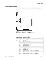
DIP Switches
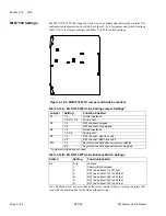
The network site address must be set for the NMU. The address, a binary number
assigned to the NMU reflecting its network site, is set using dip switch Set S1.
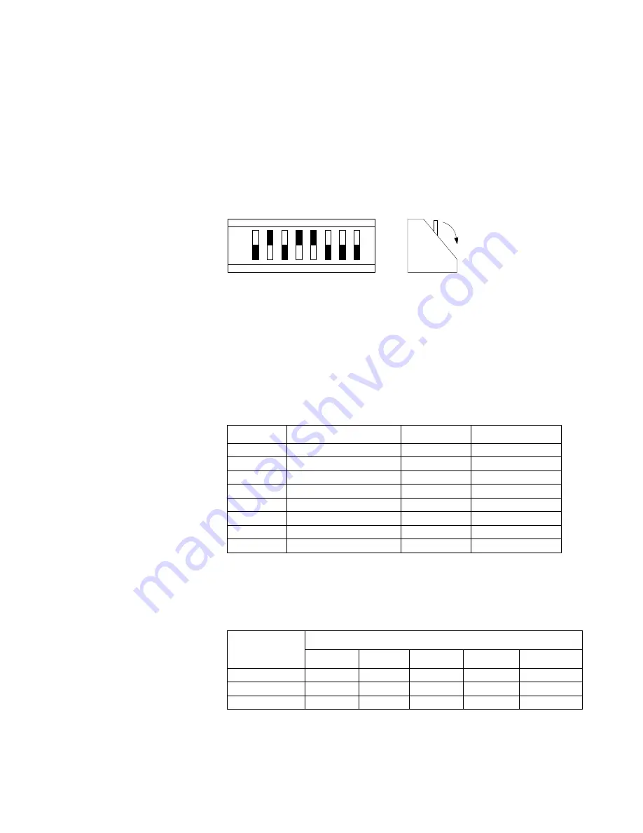
When the dip switches are set to open or closed (See Figure 3-15-3), a numeric value is
established that the system can read. Set the rockers open or closed so that the sum
represented by their numeric values equals the NMU address.
For example, to set the site address for site 26, set rockers 2, 4, and 5 to the Open
position; all others should be set to Closed. The sum of the values for rockers 2, 4,
and 5 is: 2 + 8 + 16 = 26
When the dip switch is set to Open, the address values are added to equal the site number.
When the dip switch is set to Closed, the address values are not added.
The dip switch settings for Switch Set S1 are listed in Table 3-15-B.
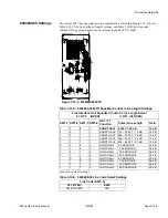
DIP Switch Set S2 settings are listed in Table 3-15-C. S2 dip switch positions 5, 7, and 8
are used to configure NMU for 3-port or 4-port bridge configuration.
Table 3-15-B. NMU Switch S1 Settings
Rocker
Function
Open
Closed
1
Site Address 1
Added
Ignored
2
Site Address 2
Added
Ignored
3
Site Address 4
Added
Ignored
4
Site Address 8
Added
Ignored
5
Site Address 16
Added
Ignored
6
Site Address 32
Added
Ignored
7
Site Address 64
Added
Ignored
8
Site Address 128
Added
Ignored
Table 3-15-C. NMU Switch S2 Settings
Function
Rocker Positions
1-4
5
6
7
8
Site Master
Open
Closed
Open
Closed
Closed
Slave
Open
Open
Open
Closed
Closed
4-Port Bridge*
Open
Open
Open
Open
Open
* On NMU part number MLN7481C only
F
-0
7
9
3
b
O
p
e
n
C
lo
s
e
d
1
2
3
4
5
6
7
8
1
2
4
8
1
6 3
2 6
4 1
2
8
V
a
lu
e
s
O
p
e
n
C
lo
s
e
d
Figure 3-15-3. DIP Switch S1 Values
Содержание CM7
Страница 2: ......
Страница 4: ...Page iv 5 04 05 CM7 8 100Base T System User s Manual ...
Страница 16: ...Glossary Page xvi CM System Users Manual X Y Z ...
Страница 24: ...Microwave Networks CM7 8 100Base T System User s Manual Pagexxiv ...
Страница 62: ...Chapter 2 Operation Page 2 18 5 02 05 CM 100Base T System User s Manual ...
Страница 64: ...Chapter 3 Module Descriptions Page 3 2 CM7 8 100Base T ...
Страница 88: ...Section 3 3 Transmitter Unit Page 3 3 6 CM7 8 System User s Manual ...
Страница 96: ...Section 3 5 RF Power Supply Unit Page 3 5 4 CM System User s Manual ...
Страница 100: ...Section 3 6 SP Power Supply Unit Page 3 6 4 CM System User s Manual ...
Страница 106: ...Section 3 7 Alarm and Control Unit Page 3 7 6 11 18 03 CM 100Base T System User s Manual ...
Страница 124: ...Section 3 11 SYNDES Page 3 11 6 CM System User s Manual ...
Страница 130: ...Section 3 12 SCU Page 3 12 6 11 18 03 CM 100Base T System User s Manual ...
Страница 138: ...Section 3 13 OWU Page 3 13 8 CM System User s Manual ...
Страница 150: ...Section 3 15 NMU Page 3 15 6 CM System User s Manual ...
Страница 192: ...Chapter 5 Verification Page 5 20 CM System User s Manual ...
Страница 194: ...Chapter 6 Maintenance Page 6 2 7 23 03 CM 100Base T System User s Manual ...
Страница 224: ...Chapter 6 Maintenance Page 6 32 7 23 03 CM 100Base T System User s Manual ...
Страница 225: ...CM System User s Manual Page 1 Place any site research or reference material here Site Engineering ...
Страница 226: ...Site Engineering Page 2 CM System User s Manual ...
Страница 230: ...Appendix A T I Curves Page A 4 CM7 8 100Base T System User s Manual ...
Страница 267: ...Microwave Networks CM System User s Manual PageB 37 ...
Страница 268: ...Appendix B QuikLink Page B 38 CM System User s Manual ...
Страница 282: ...Appendix D Alarm Codes Page D 6 5 02 05 CM 100Base T System User s Manual ...
Страница 290: ...Appendix E Setting Frequency Page E 8 CM7 8 System User s Manual ...
Страница 312: ...CM7 8 100Base T System User s Manual Page I 4 Microwave Networks ...


