Configuration and Use Manual
65
Integrating the Meter with the Control System
Op
eratio
n
App
e
ndi
ces
Mai
n
tenan
c
e and
T
roub
le
sh
oo
tin
g
Com
m
is
si
on
in
g
Configuration
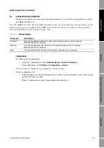
To configure Added Damping:
•
Using the Communicator, select
Detailed Setup > Config Outputs > Channel Setup >
AO Setup
.
•
Using ProLink II, click
ProLink > Configuration > Analog Output
.
Note: You cannot configure Added Damping with the display.
6.2.5
mA output fault action and fault value
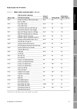
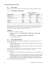
The Fault Action parameter specifies the state to which the mA output will be forced if the transmitter
encounters an internal fault condition. Options are shown in Table 6-4.
Example
Configuration:
•
Flow Damping: 1
•
mA output process variable: Mass flow
•
Added Damping: 2
As a result, a change in mass flow will be reflected in the mA output
over a time period that is greater than 3 seconds. The exact time
period is calculated by the transmitter according to internal algorithms
which are not configurable.
Table 6-4
mA output fault actions and values
Fault action
Output scale
Fault output value
Upscale
N/A
21–24 mA (user-configurable; default: 22 mA)
Downscale
12–20 mA
10.5–11.8 mA (user-configurable; default: 11.0 mA)
4–20 mA
1.0–3.6 mA (user-configurable; default: 2.0 mA)
Internal zero
N/A
Goes to the mA output level associated with a process variable value of 0
(zero), as determined by URV and LRV values.
None
N/A
Tracks data for the assigned process variable; no fault action
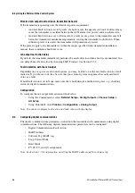
When configuring fault behavior, ensure that the configured fault action does not cause measurement
error or process upset, and that your control system can recognize fault conditions. For fault indication,
use the appropriate combination of mA output fault action, digital communications fault action, and
checking status via digital communications (e.g., HART command 48).
If you set the mA Output Fault Action to None, be sure to set the Digital Communications Fault Action to
None (see Section 6.3.1). If you do not, the mA output will not report actual process data, and this may
result in measurement error or unintended consequences for your process.
Содержание 2200S
Страница 8: ...vi Micro Motion Model 2200S Transmitters ...
Страница 12: ...4 Micro Motion Model 2200S Transmitters ...
Страница 32: ...24 Micro Motion Model 2200S Transmitters ...
Страница 38: ...30 Micro Motion Model 2200S Transmitters ...
Страница 68: ...60 Micro Motion Model 2200S Transmitters ...
Страница 92: ...84 Micro Motion Model 2200S Transmitters ...
Страница 102: ...94 Micro Motion Model 2200S Transmitters ...
Страница 110: ...102 Micro Motion Model 2200S Transmitters ...
Страница 130: ...122 Micro Motion Model 2200S Transmitters ...
Страница 134: ...126 Micro Motion Model 2200S Transmitters ...
Страница 150: ...142 Micro Motion Model 2200S Transmitters ...
Страница 156: ...148 Micro Motion Model 2200S Transmitters ...
Страница 157: ......

