


Operation
capaNCDT 6500
Page 31
5.5
Triggering
The DT6530 can be operated
-
by a trigger input, see
Fig. 30
, or
-
via a software command, see Chap.
6.4.3
.
In addition the trigger mode must be activated and a data rate, which is greater than the
maximum trigger frequency, must be set.
Controller
I = 5 ... 45 mA
100 Ohm
Trigger in
13
32
GND Trigger
U Trigger
(TTL-Pegel)
U =
ca. 1 V
F
Fig. 30 Trigger input
There are three possible settings regarding the trigger input:
-
Trigger mode 1 (rising edge): At each rising flank per channel one measured value is
sent. The data rate set has to be higher than the maximum trigger frequency. If trigge-
ring is effected faster than the set data rate, some measured values are sent twice
due to the fact that no further measured values have been generated by the analogue
digital converter yet.
-
Trigger mode 2 (high level): As long as a logical high level is connected to the trigger
input, measured values are sent thanks to the data rate set.
-
Trigger mode 3 (gate rising edge): At the first rising flank on the trigger input, the
controller starts to send measured values by means of the data rate set. At the second
rising flank the controller stops to send measured values et cetera.
Irrespective of the trigger mode set, one single measured value per channel can be
called up by means of a software command, see Chap.
6.4.3
.
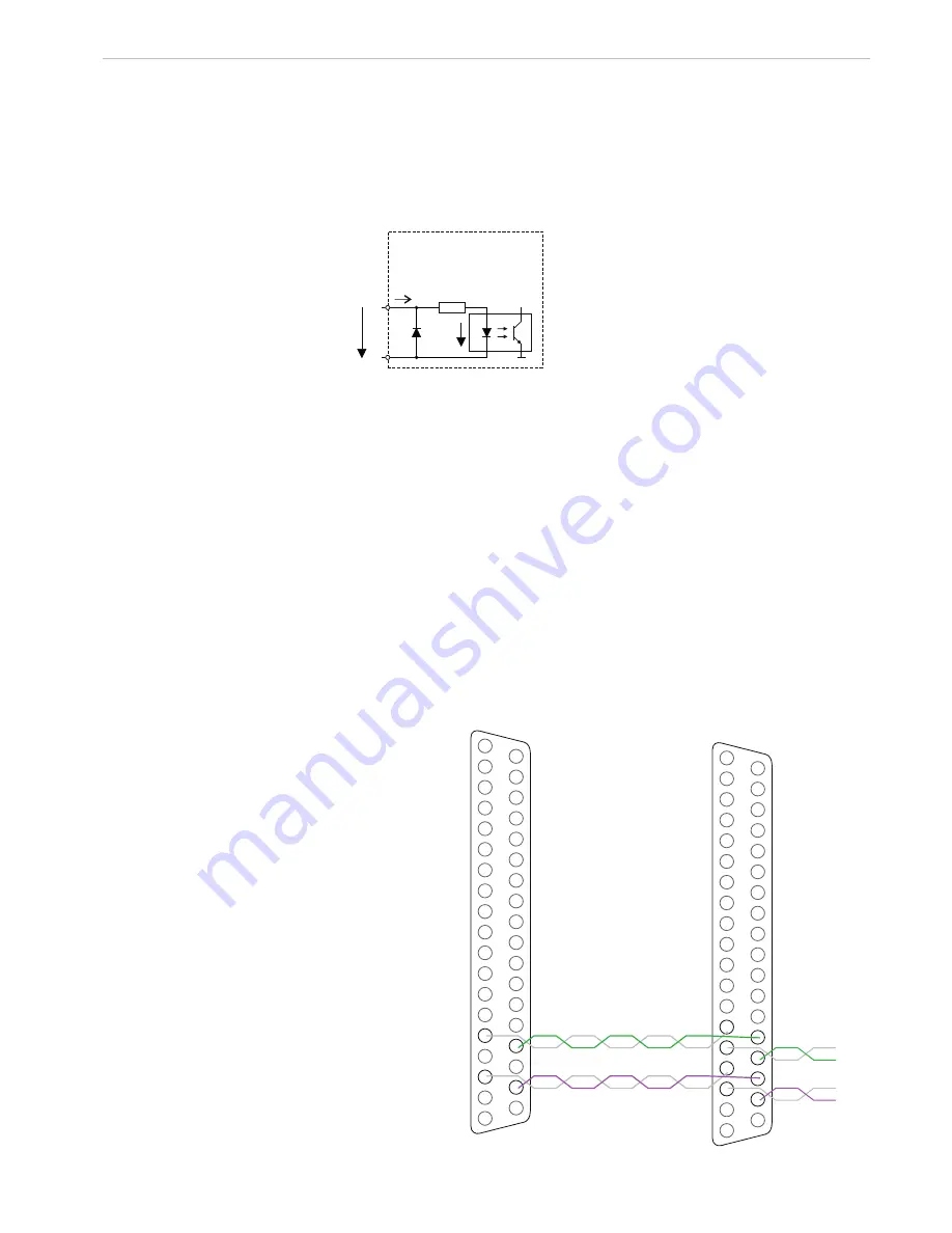
5.6
Synchronization
Up to 8 controllers can
be synchronized via the
37-pin Sub-D female
connector.
To do this, connect all
SYNC_OUT outputs
to the corresponding
Sync_in inputs of the
subsequent controller.
Use twisted pair for the
matching signals.
1
17
15
36
34
1
17
16
15
14
36
35
34
33
Controller 1
Controller 2
Fig. 31 Synchronization wiring for two controllers
Содержание capaNCDT 6500
Страница 67: ......


