


3.8
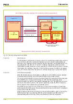
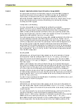
Measured Data Input (Function Group MEASI)
There is a second optional analog module available for the P631. In addition to
the analog (I/O) module
Y with analog inputs and outputs there is now a second
analog module obtainable, the temperature p/c board (also called the RTD
module).
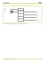
When the P631 is equipped with the analog (I/O) module Y it has two analog
inputs available for measured data input. Direct current is fed to the P631
through the 20 mA analog input (input channel 1). The other input is designed for
connection of a PT 100 resistance thermometer.
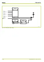
The temperature p/c board (the RTD module) mounted in the P631 has 9 analog
inputs available to connect temperature sensors T1 to T9. These analog inputs
are designed for connection of PT 100, Ni 100 or Ni 120 resistance
thermometers.
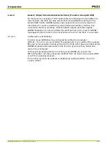
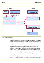
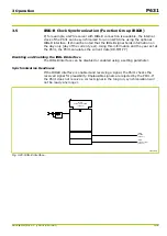
The input current I
DC
present at the analog (I/O) module Y is displayed as a
measured operating value. The current that is conditioned for monitoring
purposes (I
DC,lin
) is also displayed as a measured operating value. In addition, it is
monitored by the Limit Value Monitoring function to detect whether it exceeds or
falls below set thresholds (see “Limit Value Monitoring”).
The measured temperatures are also displayed as measured operating values
and monitored by the Limit Value Monitoring function to determine whether they
exceed or fall below set thresholds (see “Limit Value Monitoring”).
All measured variables are also forwarded to the Thermal Overload Protection
function. With this protection it is possible to set whether the PT 100 resistance
thermometer, the 20 mA analog input or – if configured – one of the temperature
sensors T1 to T9 is to be used for the thermal replica (see “Thermal Overload
Protection”).
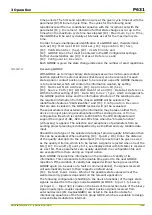
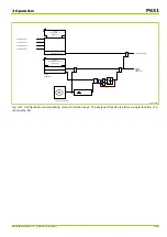
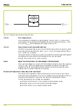
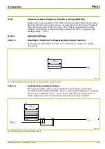
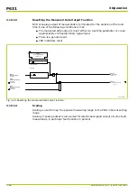
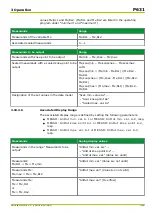
Disabling or Enabling the Measured Data Input Function
The Measured Data Input function can be disabled or enabled via setting
parameters.
S8Z52H1A
MEASI:
General enable USER
[ 011 100 ]
MEASI:
Enabled
[ 035 008 ]
1: Yes
0
1
0: No
Fig. 3-23: Disabling or enabling the measured data input function.
P631
3 Operation
3-38
P631/EN M/R-11-C // P631-310-650
Содержание P631
Страница 2: ......
Страница 4: ......
Страница 7: ...Changes after going to press...
Страница 8: ......
Страница 16: ...P631 Table of Contents 8 P631 EN M R 11 C P631 310 650...
Страница 56: ...P631 2 Technical Data 2 28 P631 EN M R 11 C P631 310 650...
Страница 236: ...P631 3 Operation 3 180 P631 EN M R 11 C P631 310 650...
Страница 246: ...P631 4 Design 4 10 P631 EN M R 11 C P631 310 650...
Страница 266: ...P631 5 Installation and Connection 5 20 P631 EN M R 11 C P631 310 650...
Страница 276: ...6 8 Configurable Function Keys P631 6 Local Control HMI 6 10 P631 EN M R 11 C P631 310 650...
Страница 548: ...P631 10 Commissioning 10 10 P631 EN M R 11 C P631 310 650...
Страница 568: ...P631 12 Maintenance 12 8 P631 EN M R 11 C P631 310 650...
Страница 570: ...P631 13 Storage 13 2 P631 EN M R 11 C P631 310 650...
Страница 572: ...P631 14 Accessories and Spare Parts 14 2 P631 EN M R 11 C P631 310 650...
Страница 576: ...P631 15 Order Information 15 4 P631 EN M R 11 C P631 310 650...
Страница 582: ...P631 A2 Internal Signals A2 4 P631 EN M R 11 C P631 310 650...
Страница 608: ...P631 A4 Telecontrol Interfaces A4 18 P631 EN M R 11 C P631 310 650...
Страница 637: ......


