


3.4.4.1.2
Ethernet Module
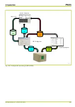
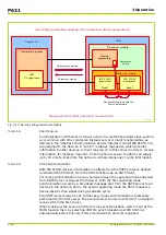
The optional Ethernet module provides an RJ45 connection and a fiber optic
interface where an Ethernet network can be connected. The selection which of
the two interfaces is to be used to connect to the Ethernet network is made by
setting the parameter [IC]: Media.
Setting parameters identified by “[IC]:…” in the IEC function group are set with the
“IED Configurator”. They cannot be modified from the local control panel (HMI) or
with the operating program.
There are two ordering variants available for the fiber-optic interface: the ST
connector and the SC connector both for 100 Mbit/s and 1300 nm (a third variant
ST connector for 100 Mbit/s and 1300 nm is pending). The RJ45 connector
supports 10 Mbit/s and 100 Mbit/s.
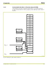
The optional Ethernet module additionally provides an RS485 interface for
remote access with the MiCOM S1 support software (function group COMM2).
The P631 may be equipped with the optional Ethernet module only as an
alternative to the standard optional communication module. Therefore the
Ethernet-based communication protocol IEC 61850 is available only as an
alternative to function group COMM1.
3.4.4.1.3
Activating and Enabling
The IEC function group can be activated by setting the parameter
IEC: Function group IEC. This parameter is only visible if the optional
Ethernet communication module is fitted to the P631. After activation of IEC, all
data points associated with this function group (setting parameters, binary state
signals etc.) become visible.
The function can then be enabled or disabled by setting IEC: General enable
USER.
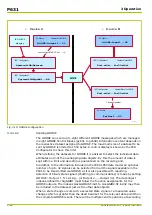
The setting parameters from the IEC function group as well as the related
function groups GOOSE and GSSE are not automatically active in the P631. The
P631 features two memory "banks" one of which includes the active setting
parameters. The other memory bank is used with the configuration procedure for
parameters from the
IED Configurator
and the operating system. Specific project-
related extensions of the IEC 61850 parameters from the
IED Configurator
are
loaded into the P631 by downloading a .MCL file. The inactive communication
parameters are activated by executing the command IEC: Switch Config.
Bank. This command may also be issued from the
IED Configurator
.
P631
3 Operation
3-22
P631/EN M/R-11-C // P631-310-650
Содержание P631
Страница 2: ......
Страница 4: ......
Страница 7: ...Changes after going to press...
Страница 8: ......
Страница 16: ...P631 Table of Contents 8 P631 EN M R 11 C P631 310 650...
Страница 56: ...P631 2 Technical Data 2 28 P631 EN M R 11 C P631 310 650...
Страница 236: ...P631 3 Operation 3 180 P631 EN M R 11 C P631 310 650...
Страница 246: ...P631 4 Design 4 10 P631 EN M R 11 C P631 310 650...
Страница 266: ...P631 5 Installation and Connection 5 20 P631 EN M R 11 C P631 310 650...
Страница 276: ...6 8 Configurable Function Keys P631 6 Local Control HMI 6 10 P631 EN M R 11 C P631 310 650...
Страница 548: ...P631 10 Commissioning 10 10 P631 EN M R 11 C P631 310 650...
Страница 568: ...P631 12 Maintenance 12 8 P631 EN M R 11 C P631 310 650...
Страница 570: ...P631 13 Storage 13 2 P631 EN M R 11 C P631 310 650...
Страница 572: ...P631 14 Accessories and Spare Parts 14 2 P631 EN M R 11 C P631 310 650...
Страница 576: ...P631 15 Order Information 15 4 P631 EN M R 11 C P631 310 650...
Страница 582: ...P631 A2 Internal Signals A2 4 P631 EN M R 11 C P631 310 650...
Страница 608: ...P631 A4 Telecontrol Interfaces A4 18 P631 EN M R 11 C P631 310 650...
Страница 637: ......


