


»
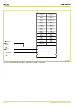
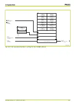
Device A
»
Device B
GOOSE: Output 1 ... 32
S1 Studio
System/GosGGIO2
System/LLN0/gcb01 ... 08
System/LLN0/Dataset
System/GosGGIO2.ST.ind1 ... 32
IEC 61850
Mapping
MCL
Pos1.stVal ... Pos32.stVal
System/DevGosGGIO3
Pos1.stVal ... Pos32.stVal
System/GosGGIO1
Ext.Dev 1 … 32
S1 Studio
GOOSE: Input 1 ... 32
S1 Studio
19Z7003A
IED Configurator
IED Configurator
IED Configurator
IED Configurator
Fixed assignment
x
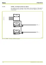
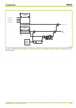
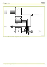
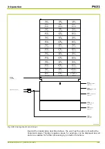
Fig. 3-18: GOOSE configuration.
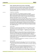
3.4.4.2.2
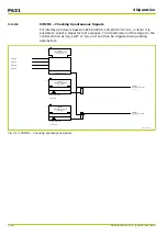
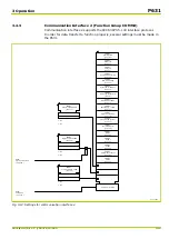
Sending GOOSE
The GOOSE can send up to eight different GOOSE messages which are managed
in eight GOOSE Control Blocks (gcb01 to gcb08). Information content depends on
the respective dataset assigned to GOOSE. The maximum size of a dataset to be
sent by GOOSE is limited to 1500 bytes. A control display is shown by the IED
Configurator to check this limit.
When defining the datasets for GOOSE it is advised to select the individual data
attributes and not the overlapping data objects. By this the amount of data is
kept within a limit and decoding is guaranteed on the receiving end.
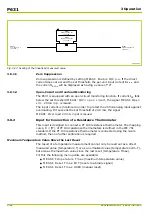
In addition to the information included in the IEC 61850 data model an optional
number of up to 32 signals can be selected from all the signals available in the
P631 to be transmitted via GOOSE, as it is also possible with reporting.
Selection of binary state signals (shuttling to communications) is made by setting
GOOSE: Output 1 fct.assig.. (or Output 2, ..., Output 32). The data object
indexes defined for SigGGIO1 must follow the function assignments for the
GOOSE outputs. The indexes GosGGIO2.ST.ind1 to GosGGIO2.ST.ind32 may then
be included in the datasets just as the other data objects.
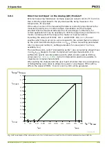
When a state change occurs with a selected state signal or a measured value
changes which is greater than the dead band set for the relevant data point then
the complete GOOSE is sent. There will be multiple send repetitions at ascending
P631
3 Operation
3-28
P631/EN M/R-11-C // P631-310-650
Содержание P631
Страница 2: ......
Страница 4: ......
Страница 7: ...Changes after going to press...
Страница 8: ......
Страница 16: ...P631 Table of Contents 8 P631 EN M R 11 C P631 310 650...
Страница 56: ...P631 2 Technical Data 2 28 P631 EN M R 11 C P631 310 650...
Страница 236: ...P631 3 Operation 3 180 P631 EN M R 11 C P631 310 650...
Страница 246: ...P631 4 Design 4 10 P631 EN M R 11 C P631 310 650...
Страница 266: ...P631 5 Installation and Connection 5 20 P631 EN M R 11 C P631 310 650...
Страница 276: ...6 8 Configurable Function Keys P631 6 Local Control HMI 6 10 P631 EN M R 11 C P631 310 650...
Страница 548: ...P631 10 Commissioning 10 10 P631 EN M R 11 C P631 310 650...
Страница 568: ...P631 12 Maintenance 12 8 P631 EN M R 11 C P631 310 650...
Страница 570: ...P631 13 Storage 13 2 P631 EN M R 11 C P631 310 650...
Страница 572: ...P631 14 Accessories and Spare Parts 14 2 P631 EN M R 11 C P631 310 650...
Страница 576: ...P631 15 Order Information 15 4 P631 EN M R 11 C P631 310 650...
Страница 582: ...P631 A2 Internal Signals A2 4 P631 EN M R 11 C P631 310 650...
Страница 608: ...P631 A4 Telecontrol Interfaces A4 18 P631 EN M R 11 C P631 310 650...
Страница 637: ......


