


3.7
Configuration and Operating Mode of the Binary Inputs
(Function Group INP)
The P631 has opto coupler inputs for processing binary signals from the
substation. The functions that will be activated in the P631 by triggering these
binary signal inputs are defined by the configuration of the binary signal inputs.
In order to ensure that during normal operation the P631 will recognize an input
signal, it must persist for at least 20 ms. With the occurrence of a general
starting this time period may have to be increased to 40 ms under unfavorable
conditions.
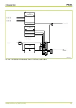
Configuring the Binary Inputs
One function can be assigned to each binary signal input by configuration. The
same function can be assigned to several signal inputs. Thus one function can be
activated from several control points having different signal voltages.
It should be noted that time-critical applications such as time synchronization
commands should not be mapped to the binary signal inputs of the analog I/O
module as these have an increased reaction time due to internal processing.
In this technical manual, it is assumed that the required functions (marked “EXT”
in the address description) have been assigned to binary signal inputs by
configuration.
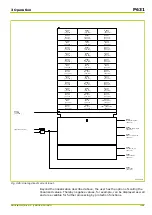
Operating Mode of the Binary Inputs
The operating mode for each binary signal input can be defined. The user can
specify whether the presence (
Active "high"
mode) or absence (
Active "low"
mode) of a voltage shall be interpreted as the logic ‘1’ signal. The display of the
state of a binary signal input – "low" or "high" – is independent of the setting for
the operating mode of the signal input.
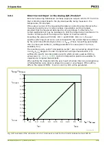
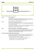
Filter Function
An additional filter function may be enabled in order to suppress transient
interference peaks at the logic signal inputs (operating modes
Active "high", filt.
or
Active "low", filt.
). With this function enabled a status change at the binary
logic input is only signaled when the input signal remains at a steady signal level
during a set number of sampling steps (sampling step size = period / 20). The
number of sampling steps is set at parameter INP: Filter.
P631
3 Operation
3-36
P631/EN M/R-11-C // P631-310-650
Содержание P631
Страница 2: ......
Страница 4: ......
Страница 7: ...Changes after going to press...
Страница 8: ......
Страница 16: ...P631 Table of Contents 8 P631 EN M R 11 C P631 310 650...
Страница 56: ...P631 2 Technical Data 2 28 P631 EN M R 11 C P631 310 650...
Страница 236: ...P631 3 Operation 3 180 P631 EN M R 11 C P631 310 650...
Страница 246: ...P631 4 Design 4 10 P631 EN M R 11 C P631 310 650...
Страница 266: ...P631 5 Installation and Connection 5 20 P631 EN M R 11 C P631 310 650...
Страница 276: ...6 8 Configurable Function Keys P631 6 Local Control HMI 6 10 P631 EN M R 11 C P631 310 650...
Страница 548: ...P631 10 Commissioning 10 10 P631 EN M R 11 C P631 310 650...
Страница 568: ...P631 12 Maintenance 12 8 P631 EN M R 11 C P631 310 650...
Страница 570: ...P631 13 Storage 13 2 P631 EN M R 11 C P631 310 650...
Страница 572: ...P631 14 Accessories and Spare Parts 14 2 P631 EN M R 11 C P631 310 650...
Страница 576: ...P631 15 Order Information 15 4 P631 EN M R 11 C P631 310 650...
Страница 582: ...P631 A2 Internal Signals A2 4 P631 EN M R 11 C P631 310 650...
Страница 608: ...P631 A4 Telecontrol Interfaces A4 18 P631 EN M R 11 C P631 310 650...
Страница 637: ......


