
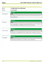


Now blocking can be cleared as follows (
Par/Func/Glob
menu branch):
●
MAIN: Device on-line =
Yes (= on)
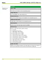
10.2.2
Testing
By using the signals and displays generated by the P631, it is possible to
determine whether the P631 is correctly set and properly interconnected with the
station. Signals are signaled by output relays and LED indicators and entered into
the event memory. In addition, the signals can be checked by selecting the
appropriate signal in the menu tree.
If the user does not wish the circuit breaker to operate during protection testing,
the trip commands can be blocked through MAIN: Trip cmd.block. USER
(
Par/Func/Glob
menu branch) or an appropriately configured binary signal input.
If circuit breaker testing is desired, it is possible to issue a trip command for
100 ms through MAIN: Man. trip cmd. USER (
Oper/CtrlTest
menu branch) or
an appropriately configured binary signal input. Selection of the trip command
from the integrated local control panel is password-protected (see
).
The manual trip command is not executed unless the manual trip is included in the
selection of possible functions to effect a trip (in the configuration of trip
commands).
If the P631 is connected at substation control level, the user is advised to
activate the test mode via MAIN: Test mode USER (
Par/Func/Glob
menu
branch) or an appropriately configured binary signal input. The telegrams are
then identified accordingly (reason for transmission: test mode).
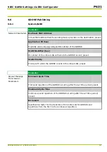
10.2.3
Checking the Binary Signal Inputs
By selecting the corresponding state signal (
Oper/Cycl/Phys
menu branch), it is
possible to determine whether the input signal that is present is recognized
correctly by the device. The values displayed have the following meanings:
●
"Low"
: Not energized.
●
"High"
: Energized.
●
Without function
: No functions are assigned to the binary signal input.
This display appears regardless of the binary signal input mode selected.
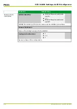
10.2.4
Checking the Output Relays
It is possible to trigger the output relays for a settable time period for test
purposes (time setting at OUTP: Hold-time for test in
Oper/CtrlTest
menu
branch). First select the output relay to be tested (OUTP: Relay assign.
f.test,
Oper/CtrlTest
menu branch).
Test triggering then occurs via OUTP: Relay test (
Oper/CtrlTest
menu branch).
Warning!
⚫
Before starting the test, open any triggering circuits for external devices so
that no inadvertent switching operations will take place.
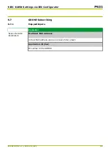
10.2.5
Checking the Protection Function
Four parameter subsets are stored in the P631, one of which is activated. Before
checking the protective function, the user should determine which parameter
10 Commissioning
P631
P631/EN M/R-11-C // P631-310-650
10-5
Содержание P631
Страница 2: ......
Страница 4: ......
Страница 7: ...Changes after going to press...
Страница 8: ......
Страница 16: ...P631 Table of Contents 8 P631 EN M R 11 C P631 310 650...
Страница 56: ...P631 2 Technical Data 2 28 P631 EN M R 11 C P631 310 650...
Страница 236: ...P631 3 Operation 3 180 P631 EN M R 11 C P631 310 650...
Страница 246: ...P631 4 Design 4 10 P631 EN M R 11 C P631 310 650...
Страница 266: ...P631 5 Installation and Connection 5 20 P631 EN M R 11 C P631 310 650...
Страница 276: ...6 8 Configurable Function Keys P631 6 Local Control HMI 6 10 P631 EN M R 11 C P631 310 650...
Страница 548: ...P631 10 Commissioning 10 10 P631 EN M R 11 C P631 310 650...
Страница 568: ...P631 12 Maintenance 12 8 P631 EN M R 11 C P631 310 650...
Страница 570: ...P631 13 Storage 13 2 P631 EN M R 11 C P631 310 650...
Страница 572: ...P631 14 Accessories and Spare Parts 14 2 P631 EN M R 11 C P631 310 650...
Страница 576: ...P631 15 Order Information 15 4 P631 EN M R 11 C P631 310 650...
Страница 582: ...P631 A2 Internal Signals A2 4 P631 EN M R 11 C P631 310 650...
Страница 608: ...P631 A4 Telecontrol Interfaces A4 18 P631 EN M R 11 C P631 310 650...
Страница 637: ......


