Parameter
Address
Default
Min
Max
Unit
Logic Diagram
[spacer]
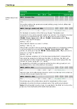
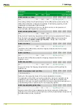
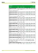
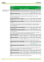
DIFF: Idiff>>> PSx
072 144
073 144
074 144
075 144
30.0
2.5
30.0
Iref
[spacer]
This setting defines the threshold value for the differential current where the
differential protection is triggered regardless of restraining quantity, inrush
stabilization and saturation discriminator.
Note: If the threshold is set too low, the P631 can trip in the presence of
external faults with transformer saturation.
[spacer]
DIFF: Idiff>(CTS) PSx
080 000
081 000
082 000
083 000
0.20
0.10
30.00
Iref
[spacer]
If the Current Transformer Supervision (CTS) function has detected a CT failure,
then the basic operating threshold DIFF: Idiff> PSx can be raised to a
settable safe value DIFF: Idiff>(CTS) PSx. Please refer to the CTS
function section for more details.
[spacer]
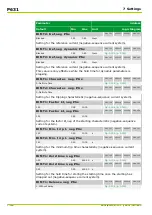
DIFF: m1 PSx
072 145
073 145
074 145
075 145
0.30
0.10
1.50
[spacer]
Gradient of the differential protection tripping characteristic for the range
0.5·I
diff>
< I
R
≤
I
R,m1
.
[spacer]
DIFF: m2 PSx
072 146
073 146
074 146
075 146
0.70
0.10
1.50
[spacer]
Gradient of the differential protection tripping characteristic for the
range I
R
> I
R,m2
.
[spacer]
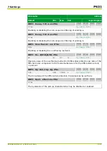
DIFF: IR,m2 PSx
072 147
073 147
074 147
075 147
4.0
1.5
10.0
Iref
[spacer]
Knee point where the tripping characteristic continues with the setting for
gradient m2.
[spacer]
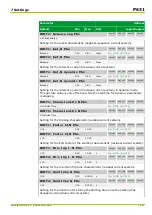
DIFF: Op.mode rush rst.PSx
072 148
073 148
074 148
075 148
1: Not phase-selective
[spacer]
Setting for the operating mode of the inrush stabilization function.
For application of the P631 as machine protection, harmonic restraint can be
disabled by way of this setting. For application of the P631 as transformer
protection, the user can select whether the harmonic restraint should operate in
cross-blocking mode or selectively for one measuring system.
[spacer]
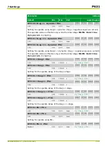
DIFF: RushI(2f0)/I(f0) PSx
072 159
073 159
074 159
075 159
20
10
50
%
[spacer]
Operate value of the inrush stabilization (harmonic restraint) of differential
protection as a ratio of the second harmonic with the fundamental component of
the differential current, in percent.
P631
7 Settings
7-106
P631/EN M/R-11-C // P631-310-650
Содержание P631
Страница 2: ......
Страница 4: ......
Страница 7: ...Changes after going to press...
Страница 8: ......
Страница 16: ...P631 Table of Contents 8 P631 EN M R 11 C P631 310 650...
Страница 56: ...P631 2 Technical Data 2 28 P631 EN M R 11 C P631 310 650...
Страница 236: ...P631 3 Operation 3 180 P631 EN M R 11 C P631 310 650...
Страница 246: ...P631 4 Design 4 10 P631 EN M R 11 C P631 310 650...
Страница 266: ...P631 5 Installation and Connection 5 20 P631 EN M R 11 C P631 310 650...
Страница 276: ...6 8 Configurable Function Keys P631 6 Local Control HMI 6 10 P631 EN M R 11 C P631 310 650...
Страница 548: ...P631 10 Commissioning 10 10 P631 EN M R 11 C P631 310 650...
Страница 568: ...P631 12 Maintenance 12 8 P631 EN M R 11 C P631 310 650...
Страница 570: ...P631 13 Storage 13 2 P631 EN M R 11 C P631 310 650...
Страница 572: ...P631 14 Accessories and Spare Parts 14 2 P631 EN M R 11 C P631 310 650...
Страница 576: ...P631 15 Order Information 15 4 P631 EN M R 11 C P631 310 650...
Страница 582: ...P631 A2 Internal Signals A2 4 P631 EN M R 11 C P631 310 650...
Страница 608: ...P631 A4 Telecontrol Interfaces A4 18 P631 EN M R 11 C P631 310 650...
Страница 637: ......

