
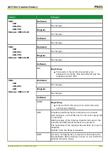


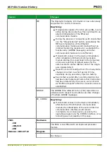

Version
Changes
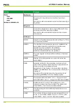
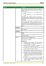
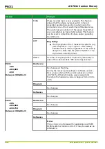
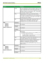
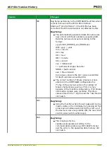
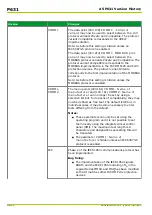
IEC
Implementation of active monitoring of the
communications data links to logged-on clients with the
parameter (104 062) IEC: TCP keep-alive timer.
Implementation of an automatic switchover to daylight
saving time, activated by parameter (104 219) IEC:
Switch.dayl.sav.time. Switchover times for the
automatic switch to daylight saving time are governed
by the following settings:
●
(104 220) IEC: Dayl.sav.time start
●
(104 221) IEC: Dayl.sav.time st. d
●
(104 222) IEC: Dayl.sav.time st. m
●
(104 223) IEC: Dayl.sav.t.st.0:00 +
●
(104 225) IEC: Dayl.sav.time end
●
(104 226) IEC: Dayl.sav.time end d
●
(104 227) IEC: Dayl.sav.time end m
●
(104 228) IEC: Dayl.sav.t.end 0:00+
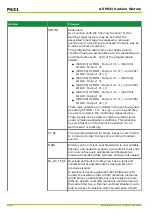
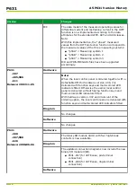
A second SNTP server may now be applied for time
synchronization. Should no answer be transmitted by
the first SNTP server the next request is automatically
transferred to the second SNTP server (backup
function).
●
(104 202) IEC: SNTP server 1 IP
●
(104 210) IEC: SNTP server 2 IP
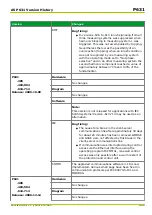
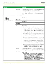
Instead of setting a router address and target network,
so as to establish a communication link to a client
situated exterior to the local network, now only the
setting of the gateway address is required via
(104 011) IEC: Gateway address.
Now “unbuffered reports” are available for all logical
nodes.
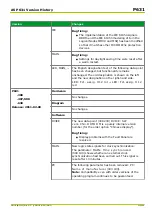
LED
The new detachable HMI provides the following
extended display functionalities:
●
The operating mode for the LED indicators has
been extended by the operating mode LED
flashing.
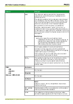
●
Two differing signals may now be assigned to the
freely configurable LED indicators (H 4 to H 16
and H 18 to H 23) to emit either red or green
light. If both assigned signals are active the
resulting LED color will be 'amber' (yellow).
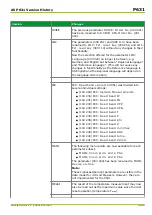
Configuration, operating mode and physical state of the
permanently configured LED indicators H1 and H17 are
now displayed via configuration parameters and
physical state signals.
P631
A5 P631 Version History
A5-12
P631/EN M/R-11-C // P631-310-650
Содержание P631
Страница 2: ......
Страница 4: ......
Страница 7: ...Changes after going to press...
Страница 8: ......
Страница 16: ...P631 Table of Contents 8 P631 EN M R 11 C P631 310 650...
Страница 56: ...P631 2 Technical Data 2 28 P631 EN M R 11 C P631 310 650...
Страница 236: ...P631 3 Operation 3 180 P631 EN M R 11 C P631 310 650...
Страница 246: ...P631 4 Design 4 10 P631 EN M R 11 C P631 310 650...
Страница 266: ...P631 5 Installation and Connection 5 20 P631 EN M R 11 C P631 310 650...
Страница 276: ...6 8 Configurable Function Keys P631 6 Local Control HMI 6 10 P631 EN M R 11 C P631 310 650...
Страница 548: ...P631 10 Commissioning 10 10 P631 EN M R 11 C P631 310 650...
Страница 568: ...P631 12 Maintenance 12 8 P631 EN M R 11 C P631 310 650...
Страница 570: ...P631 13 Storage 13 2 P631 EN M R 11 C P631 310 650...
Страница 572: ...P631 14 Accessories and Spare Parts 14 2 P631 EN M R 11 C P631 310 650...
Страница 576: ...P631 15 Order Information 15 4 P631 EN M R 11 C P631 310 650...
Страница 582: ...P631 A2 Internal Signals A2 4 P631 EN M R 11 C P631 310 650...
Страница 608: ...P631 A4 Telecontrol Interfaces A4 18 P631 EN M R 11 C P631 310 650...
Страница 637: ......


