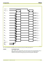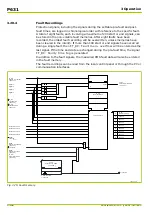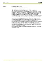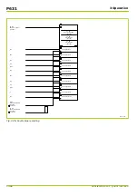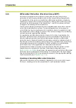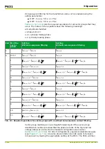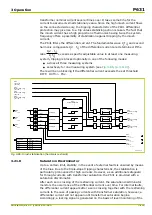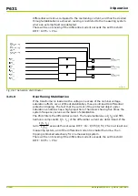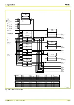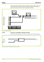
automatically form the complementary value of the set vector group ID to the
number 12 (vector group ID = 12 – set ID).
MAIN:
Phase sequence
[ 010 049 ]
62Z8010A
DIFF:
Vec.gr. ends a-b PSx
[ * ]
Parameter
set 1
set 2
set 3
set 4
DIFF:
Vec.gr. ends a-b PSx
019 010
019 040
019 041
019 042
DIFF:
0-seq. filt.a en.PSx
072 155
073 155
074 155
075 155
Parameter
set 1
set 2
set 3
set 4
DIFF:
0-seq. filt.b en.PSx
072 156
073 156
074 156
075 156
I̲am,0,a
I̲am,0,b
I̲am,A,a
I̲am,B,a
I̲am,C,a
I̲am,A,b
I̲am,B,b
I̲am,C,b
DIFF:
0-seq. filt.a en.PSx
[ * ]
DIFF:
0-seq. filt.b en.PSx
[ * ]
0: No
1: Yes
0: No
1: Yes
I̲s,y,a
I̲s,1,a
I̲s,2,a
I̲s,3,a
I̲s,1,b
I̲s,y,b
I̲s,2,b
I̲s,3,b
0
2
4
6
8
10
12
1
3
5
7
9
11
0
1
0
1
Fig. 3-81: Vector group matching and zero-sequence filtering
3.21.5
Tripping Characteristics
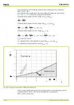
The differential and restraining current values for each measurement system are
calculated from the current values after amplitude and vector group matching.
The following equations are valid for uniformly defined current arrows relative to
the protected equipment, e.g. all the current arrows of all windings point either
towards the protected object or away from it.
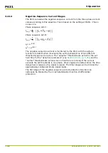
Calculation of differential and restraining currents:
I
d
,
y
=
|
I
s
,
y
,
a
+
I
s
,
y
,
b
|
I
R
,
y
= 0.5
⋅
|
I
s
,
y
,
a
−
I
s
,
y
,
b
|
The tripping characteristic of the P631 line differential protection device has two
knee points. The first knee-point depends on the setting at DIFF: Idiff> PSx
and is on the intersection with the tripping characteristic for single-side feed.
If the current transformer supervision (CTS) function is used, the basic pick-up
sensitivity DIFF: Idiff> PSx can be increased to a set value
(DIFF: Idiff>(CTS) PSx) when a CT fault is detected. See details given in the
section describing the CTS function group.
3 Operation
P631
P631/EN M/R-11-C // P631-310-650
3-115
Содержание P631
Страница 2: ......
Страница 4: ......
Страница 7: ...Changes after going to press...
Страница 8: ......
Страница 16: ...P631 Table of Contents 8 P631 EN M R 11 C P631 310 650...
Страница 56: ...P631 2 Technical Data 2 28 P631 EN M R 11 C P631 310 650...
Страница 236: ...P631 3 Operation 3 180 P631 EN M R 11 C P631 310 650...
Страница 246: ...P631 4 Design 4 10 P631 EN M R 11 C P631 310 650...
Страница 266: ...P631 5 Installation and Connection 5 20 P631 EN M R 11 C P631 310 650...
Страница 276: ...6 8 Configurable Function Keys P631 6 Local Control HMI 6 10 P631 EN M R 11 C P631 310 650...
Страница 548: ...P631 10 Commissioning 10 10 P631 EN M R 11 C P631 310 650...
Страница 568: ...P631 12 Maintenance 12 8 P631 EN M R 11 C P631 310 650...
Страница 570: ...P631 13 Storage 13 2 P631 EN M R 11 C P631 310 650...
Страница 572: ...P631 14 Accessories and Spare Parts 14 2 P631 EN M R 11 C P631 310 650...
Страница 576: ...P631 15 Order Information 15 4 P631 EN M R 11 C P631 310 650...
Страница 582: ...P631 A2 Internal Signals A2 4 P631 EN M R 11 C P631 310 650...
Страница 608: ...P631 A4 Telecontrol Interfaces A4 18 P631 EN M R 11 C P631 310 650...
Страница 637: ......

