


20
TABLE 9
Once
“OPEN” command
Activates the automation as described in Table 3 (Open function)
Twice
“Pedestrian opening” command
Activates partial opening of one or two leafs as described in Table 3
(Pedestrian
opening)
Three times
“Open only” command
Activates opening of the leaves (open - stop - open etc.)
Four times
“Close only” command
Activates closing of the leaves (close - stop - close etc.)
Five times
“Stop” command
Stops the manoeuvre
Six times
“Apartment block open” command
On opening the command has no effect, and on closing inverts movement, i.e.
opening of the leaves
Seven times
“High priority open” command
Gives command even when automation is blocked
Eight times
“Pedestrian opening 2” command
Activates partial opening of the leaf M2, equal to approx. mid-travel
Nine times
“Pedestrian opening 3” command
Activates partial opening of the two leaves, equal to approx. mid-travel
Ten times
“Open+ block automation” command
It causes an opening manoeuvre, after which the automation is blocked;
the control unit accepts no further commands with the exception of “Open high
priority” and “Release” automation
Eleven times
“Close + block automation” command
It causes a closure manoeuvre, after which the automation is blocked;
the control unit accepts no further commands with the exception of “Open high
priority” and “Release” automation
Twelve times
“Block automation” command
It causes the manoeuvre to stop and the automation to block; the control unit
accepts no further commands with the exception of “Open high priority” and “Release”
automation.
Thirteen times “Unblock automation” command
It causes the automation to be released and normal operation to resume
10.4.3 - Remote memorisation
A new radio transmitter can be memorised on the control unit without
having to use the unit itself. It is sufficient to have an “OLD” working and
memorised radio transmitter. The “NEW” radio transmitter to be memo-
rised will inherit the characteristics of the OLD one, i.e. if the OLD radio
transmitter was memorised in Mode 1, the NEW one will also be memo-
rised in Mode 1. In this case, during the memorisation stage you can
press any key on the two transmitters. If, on the other hand, the OLD
transmitter was memorised in Mode 2 you must press the key on the
OLD transmitter which corresponds to the desired command, and the
key on the NEW transmitter to which you wish to associate that com-
mand.
Holding the two transmitters, position yourself within the operating range
of the automation and perform the following operations:
01.
Press the key on the NEW radio transmitter for at least 5 s then
release it.
02.
Press the key on the OLD radio transmitter slowly 3 times.
03.
Press the key on the NEW radio transmitter slowly once.
At this point the NEW radio transmitter will be recognised by the control
unit and will assume the characteristics of the OLD one.
If there are other transmitters to be memorised, repeat all the steps
above for each new transmitter.
10.4.4 - Deleting a radio transmitter
Only if the system features a radio transmitter, you can delete it from the
memory by proceeding as follows.
If the transmitter is memorised in Mode 1, only one deletion procedure
will be needed and at step 3 you can press any key. If the transmitter is
memorised in Mode 2, one deletion procedure will be needed for each
key memorised.
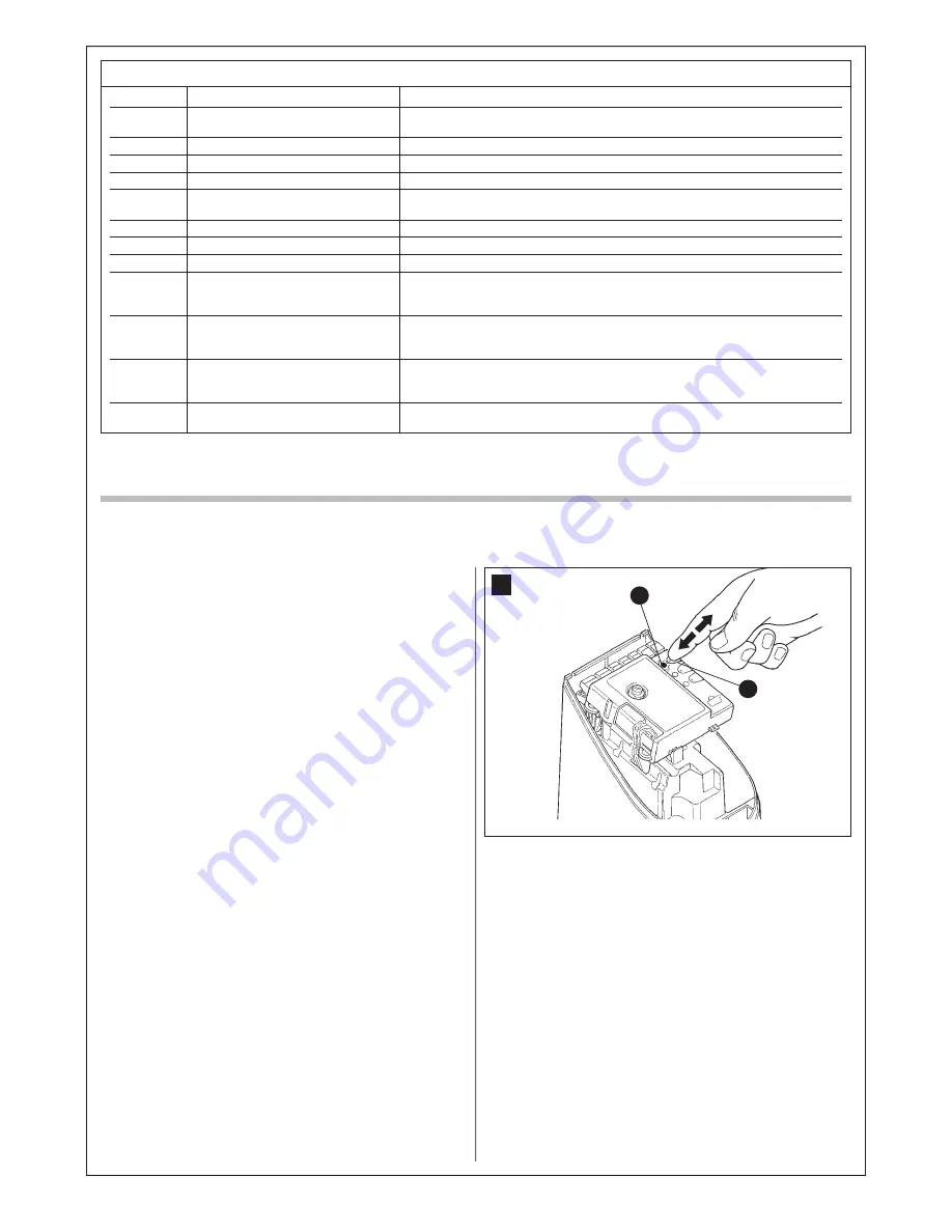
01.
Press and hold key P1
[B]
(
fig. 36
) on the control unit.
02.
Wait for the LED P1
[A]
(
fig. 36
) to switch on, so within three sec-
onds.
03.
Press the key on the radio transmitter to be deleted for at least three
seconds. If the deletion procedure is successful, the P1 LED will
flash rapidly five times. If the P1 LED flashes only once slowly, it
means that the deletion procedure has not been successful because
the transmitter is not memorised.
04.
To delete other transmitters keep key P1 pressed and repeat step
3 within 10 seconds otherwise the deletion procedure will end auto-
matically.
36
B
A
10.4.5 - Deleting all the radio transmitters
With this operation all the memorised transmitters are deleted.
01.
Press and hold key P1
[B]
(
fig. 36
) on the control unit.
02.
Wait for LED P1
[A]
(
fig. 36
) to switch on, then off and then flash 3
times.
3
Release key P1 precisely upon the third flash.
4
Wait approximately 4s for the deletion process to be completed; during
this time the P1 LED will flash very quickly.
If the procedure is successful, after a few moments the P1 LED will flash
slowly 5 times.
Содержание MhouseKit WS2S
Страница 2: ......
Страница 7: ...5 D G B C D D E F a d g d e f b b c 1 3 4 5 A B E H F I 2 L G D C A...
Страница 9: ...7 8 10 NO 11 E D C 12 13 9 A B F G...
Страница 10: ...8 M L 15 17 N O P 16 Blue Yellow Green Brown 18 19 I 14 H H...
Страница 30: ...28...
Страница 34: ......
Страница 35: ......


