background image

16

10.1.2 - Checking settings via a radio transmitter

With a radio transmitter memorised in Mode 1 the user can check settings 
at any time for each parameter, as follows:
To display the parameters, see Table 5:

01.

  Press T1 and T2 simultaneously on the radio transmitter for at least 

5 s.

02.

  Release the two keys.

03.

  Within three seconds, complete the action as specified in 

Table 5


according to the parameter to be checked.

04.

  Release the key when the flashing light starts to flash.

05.

  Count the number of flashes and, according to the number, check 

the corresponding value on Table 3.

Example: After pressing T1 and T2 for 5 s followed by T1, if the flashing 
light flashes three times, the pause time is set at 40 s.

To display the parameters, see Table 6:

01.

  Press T1 and T3 simultaneously on the radio transmitter for at least 

5 s.

02.

  Release the two keys.

03.

  Within three seconds, complete the action as specified in 

Table 6


according to the parameter to be checked.

04.

  Release the key when the flashing light starts to flash.

05.

  Count the number of flashes and, according to the number, check 

the corresponding value on Table 4.

10.2 - OPTIONAL ACCESSORIES

As well as the devices in WS2S, there are a number of optional accessories 
which may be used to integrate the automation system.

PR1:

 24 V buffer battery; in the event of a mains power failure, this guar-

antees at least 10 complete cycles.

PF:

 24 V solar power system; useful in cases in which there is no electri-

cal mains power. 

PT50:

 Pair of columns (height 500 mm) with photocell

PT100:

 Pair of columns (height 1,000 mm) with two photocells

For information on the new accessories, refer to the MHOUSE catalogue 
or visit the website www.mhouse.com.

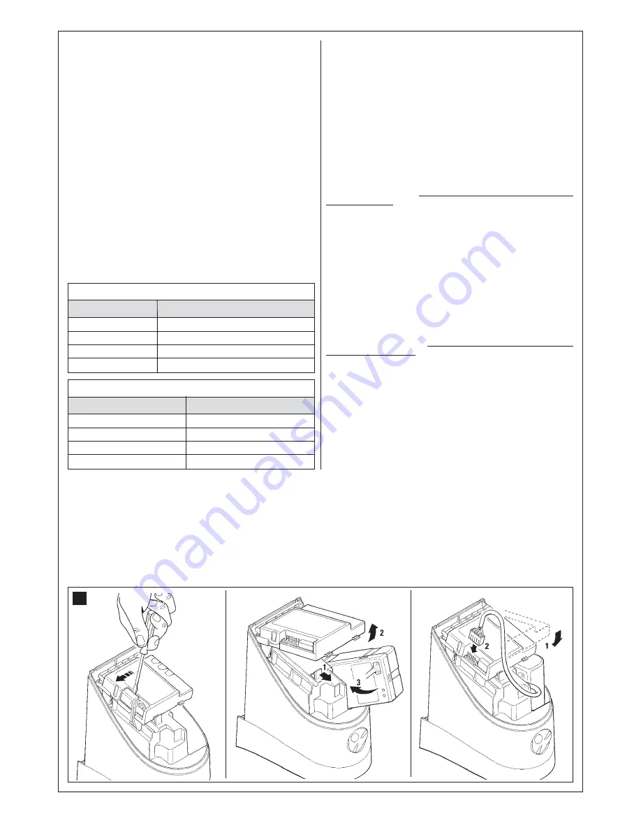
10.2.1 - Installing the PR1 buffer battery (fig. 31)

CAUTION! - The electric connection of the battery to the control 
unit must only be made after completing all installation and pro-
gramming phases, as the battery constitutes an emergency power 
supply.

To install and connect the buffer battery PR1 to the control unit, refer to 

fig. 31

 and the PR1 instruction manual.

When the automation is powered by the buffer battery, 60 seconds after 
a manoeuvre is completed, the control unit automatically switches off the 
output “ECSbus” (and all connected devices), output Flash and all leds, 
with the exception of the ECSbus led, which flashes at slower intervals; 
this indicates the “Standby” function. When the control unit receives a 
command, it restores normal operation (with a short delay). This function 
is used to reduce consumption; an important factor when the unit is pow-
ered by battery.

10.2.2 -  Installing the PF solar power supply system (fig. 32)

CAUTION! - When the automation is powered exclusively by the 
solar power system “PF”, IT MUST NEVER BE POWERED at the 
same time by the mains.

To connect the PF solar power system to the control unit, refer to 

fig. 32


and the PF instruction manual.
When the automation is powered by the solar panel, 60 seconds after a 
manoeuvre is completed, the control unit automatically switches off the 
output “ECSbus” (and all connected devices), output Flash and all leds, 
with the exception of the ECSbus led, which flashes at slower intervals; 
this indicates the “Standby” function. When the control unit receives a 
command, it restores normal operation (with a short delay). This function 
is used to reduce consumption; an important factor when the unit is pow-
ered by photovoltaic panels.

31

1

2

3

Parameter

Pause Time

Pedestrian opening

Motor force

“OPEN” function

Action

Press T1 and hold it down

Press T2 and hold it down

Press T3 and hold it down

Press T4 and hold it down

TABLE 5

Parameter

Discharge on closing Motor 1

Discharge on opening Motor 1

Discharge on closing Motor 2

Discharge on opening Motor 2

Action

Press T1 and hold it down

Press T2 and hold it down

Press T3 and hold it down

Press T4 and hold it down

TABLE 6

Содержание MhouseKit WS2S

Страница 1: ...MhouseKit WS2S For power operated swing gate Installation instructions and warnings and operating manual IS0004A01EN_07 02 2012...

Страница 2: ......

Страница 3: ...12 7 2 INITIAL CHECKS 12 7 3 RECOGNITION OF CONNECTED DEVICES 12 7 4 RECOGNITION OF THE GATE LEAF OPENING AND CLOSING ANGLES 12 7 5 CHECKING THE RADIO TRANSMITTERS 12 7 6 SETTINGS 12 TESTING AND COMM...

Страница 4: ...ed conformity of the automation In consideration of this all mains connection testing commissioning and mainte nance operations must be performed exclusively by a qualified and skilled technician All...

Страница 5: ...Tx and Rx Ensure that all devices to be installed are in a sheltered location and protected against the risk of accidental impact 3 2 PRODUCT APPLICATION LIMIT Before proceeding with installation perf...

Страница 6: ...position of all connection cables Refer to the instructions in paragraph 4 2 to establish the layout of the raceways for electric cable ducting 4 1 3 Ensure all equipment and materials for work are av...

Страница 7: ...5 D G B C D D E F a d g d e f b b c 1 3 4 5 A B E H F I 2 L G D C A...

Страница 8: ...ed to the leaf material 12 Turn the leaf to the required gate open position Place the limit switch against the straight arm L and tighten the two screws M fig 15 13 Loosen screw N securing the straigh...

Страница 9: ...7 8 10 NO 11 E D C 12 13 9 A B F G...

Страница 10: ...8 M L 15 17 N O P 16 Blue Yellow Green Brown 18 19 I 14 H H...

Страница 11: ...9 OPEN STOP TX TR ECS M M FLASH STOP OPEN M M bus ECS bus ECS FLASH bus M M M M WS1SCM2 WS1SK M1 KS100 PH100 FL100 Blue Yellow Green Brown B A 20...

Страница 12: ...electrical cable in the relative terminals of both TX and RX fig 21 5 and to the blue terminal on the control board No polarity needs to be observed 07 Fix the covering shell D in fig 21 6 with the t...

Страница 13: ...11 22 A B 6 mm x4 6 mm x4 A B A B A B A A A A B B B 1 2 3 4 4 A B A B A B A B A B A B 5 6 7 8 9 11 12 10 A B A B...

Страница 14: ...urred see paragraph 10 5 Troubleshooting The connected devices recognition stage can be repeated again at any time even after the installation for example if an additional photocell is installed just...

Страница 15: ...ablish what tests should be conducted based on the risks involved and verify the compliance of the system with applicable regulations legis lation and standards in particular with all the provisions o...

Страница 16: ...am e g fig 5 risk assessment and solutions adopted manufacturer s declaration of conformity for all devices used use appendix 1 EC declaration of conformity for components of WS2S 02 Affix a dataplate...

Страница 17: ...six times Press T2 seven times Press T2 eight times Press T3 once Press T3 twice Press T3 three times Press T3 four times Press T3 five times Press T3 six times Press T3 seven times Press T3 eight ti...

Страница 18: ...ly be made after completing all installation and pro gramming phases as the battery constitutes an emergency power supply To install and connect the buffer battery PR1 to the control unit refer to fig...

Страница 19: ...te the energy consumed by the automation proceed as follows 05 On the table below select the box corresponding to the intersection between the line with the weight and the column with the opening angl...

Страница 20: ...cognition of other devices Normally the recognition of the devices connected to the ECSBus and the STOP input takes place during the installation stage However if new devices are added or old ones rem...

Страница 21: ...to memorise it If the memorisation procedure is successful the P1 LED will flash 3 times 03 If there are other transmitters to be memorised repeat step 2 within the next 10 s otherwise the memorisati...

Страница 22: ...press any key on the two transmitters If on the other hand the OLD transmitter was memorised in Mode 2 you must press the key on the OLD transmitter which corresponds to the desired command and the k...

Страница 23: ...tent the voltage value is not important approximately 10 30 VAC if there is voltage the problem is due to the lamp in this case replace the lamp with one having the same characteristics TABLE 10 fig...

Страница 24: ...rmal operation and on possible faults see Table 13 Quick flashes 1 flash 1 second pause 1 flash 2 flashes 1 second pause 2 flashes 3 flashes 1 second pause 3 flashes 4 flashes 1 second pause 4 flashes...

Страница 25: ...e is under way Action Cyclic operation Complete cyclic operation Perform the recognition phase see chapter 3 5 2 Recognition of leaf opening and closing angles Opening angle recognition phase is under...

Страница 26: ...osing of the contact causes the OPEN command STOP input For normally open contacts and or for 8 2K constant resistance type contacts or normally closed contacts with recognition of the normal status a...

Страница 27: ...1 6 m s approx 20 approx 20 Up to 10m for maximum TX RX misalignment of 5 the device can signal an obstacle even in the case of adverse weather conditions The device can be connected only to ECSBus n...

Страница 28: ...d doors AM OOK coded modulation of radio carrier 433 92 MHz Rolling code with 64 Bit code 18 billion billion combinations 4 each key can be used for the different controls of the same control unit or...

Страница 29: ...WS1SC WS1SK PH100 and FL100 conform to DIRECTIVE 2004 108 CE 108 EC OF THE EUROPEAN PARLIA MENT AND COUNCIL of 15th December 2004 regarding the approximation of member state legislation related to el...

Страница 30: ...28...

Страница 31: ...and made available to all users of the automation 11 1 Safety instructions Keep an eye on the moving door and keep at a safe dis tance until the door has completely opened or closed do not cross the...

Страница 32: ...uch that a fault or an incorrectly balanced door could cause injury 11 5 Remote control battery replacement fig 43 When the battery charge is low the range of the transmitter is significantly reduced...

Страница 33: ...ation address Complies with the essential requirements of the following directives 2006 42 EC Machinery Directive 2004 108 EEC Electromagnetic Compatibility Directive 2006 95 EEC Low Voltage Directive...

Страница 34: ......

Страница 35: ......

Страница 36: ...Mhouse is a commercial trademark owned by Nice S p a Nice S p a Via Pezza Alta 13 Z I Rustign 31046 Oderzo TV Italy Tel 39 0422 85 38 38 Fax 39 0422 85 35 85...

Отзывы: