background image

RYZ

ENGINE 5-11

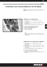
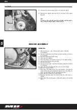
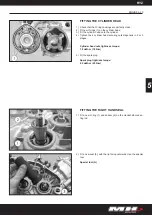
REMOVING THE CYLINDER HEAD/CYLINDER ASSEMBLY 

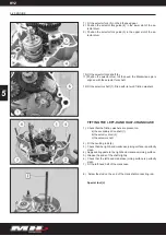
Remove the spark plug.
In the order indicated, loosen the four securing nuts on the 
cylinder head/cylinder assembly in two or three steps
Remove the four nuts and washers.
Remove the cylinder head and the two O-rings.
Remove the cylinder and the cylinder gasket.

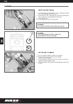
REMOVING THE PISTON

Remove one of the two circlips (1) with a pair of circlip pliers (2).
Remove the gudgeon pin.
Remove the piston.
Remove the needle bearing assembly from the end of the con-
necting rod. 

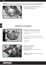
REMOVING THE THERMOSTAT VALVE

Remove the two bolts (1) from the thermostat valve (2).
Remove the thermostat valve.

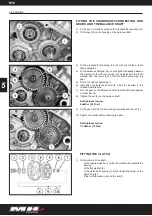
REMOVING THE TEMPERATURE SENSOR

1) 
2)

3)
4)
5)

1)
2)
3)
4)

1)
2)

5

WARNING:

There is a metal gasket to ensure the temperature
 sensor (1) remains watertight.

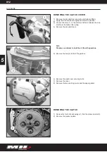
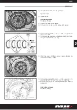
WARNING:

In refi tting, take care to position the breather hole (a) at the 
highest point.

Содержание RYZ 50 Cross C

Страница 1: ...REF OF PUBLICATION 0634111000004 1A EDITION 2007 10 USE THIS SERVICE MANUAL WITH THE RELATED MANUALS INDICATED IN THE FOREWORD TO THIS MANUAL w w w m o t o r h i s p a n i a e s SERVICE MANUAL...

Страница 2: ...at may damage the machine N B Contains special information to aid maintenance or clarify some point in the instructions WARNING This service manual has been prepared for authorised G H E ENGINEHISPA N...

Страница 3: ...ons perfectly in accordance with the speci cation When changing parts or carrying out service work that involves dismantling it is recommended to use genuine G H E ENGINEHIS PANIA S L spare parts tool...

Страница 4: ...RYZ NOTES...

Страница 5: ...RYZ CONTENTS OF SECTION SECTION GENERAL INFORMATION SPECIFICATIONS MAINTENANCE CHASSIS ENGINE ELECTRICAL SYSTEM TROUBLESHOOTING 1 2 3 4 5 6 7...

Страница 6: ...RYZ NOTES...

Страница 7: ...RYZ SECTION 1 GENERAL INFORMATION CONTENTS USING THIS MANUAL 1 2 IDENTIFICATION 1 3 Machine identi cation 1 3 Engine identi cation 1 3 GENERAL INFORMATION 1 1...

Страница 8: ...page numbers start from the beginning The numbers appear at the top of the page together with the name of the section This manual includes units of measurement in the international system SI The use o...

Страница 9: ...ted on the right hand side of the chassis This plate has the VIN VEHICLE IDENTIFICATION NUMBER engraved on it The VIN VEHICLE IDENTIFICATION NUMBER is engraved on the right hand chassis beam 2 ENGINE...

Страница 10: ...RYZ NOTES...

Страница 11: ...RYZ SECCION 2 SPECIFICATIONS CONTENTS GENERAL SPECIFICATIONS 2 2 ENGINE SPECIFICATIONS 2 2 CHASSIS SPECIFICATIONS 2 4 TIGHTENING TORQUES 2 5 SPECIFICATIONS 2 2 2...

Страница 12: ...SM 1 170 mm RYZ UB 1 150 mm 820 mm RYZ TL 97 kg RYZ SM 98 kg RYZ UB 101 kg RYZ TL 97 kg RYZ SM 98 kg RYZ UB 101 kg 255 kg 45 km h ENGINE SPECIFICATIONS ELEMENT ENGINE Engine type Make Cubic capacity S...

Страница 13: ...with the throttle and driven by geared take off from the crankshaft The oil is injected directly into the carburettor Semi synthetic Motul 510 2St special anti smoke two stroke oil 1 1 Litres Circulat...

Страница 14: ...85 X16 Disk with hydraulic calliper RYZ TL 90 90X21 RYZ SM 100 80X17 RYZ UB 90 90X16 RYZ TL 1 9 1 bar RYZ SM 2 0 1bar RYZ UB 2 3 1 bar RYZ TL 2 5 X18 RYZ SM 3 5 X17 RYZ UB 2 5 X16 RYZ TL 120 80X18 RYZ...

Страница 15: ...ion Travel of central single hydraulic shock absorber STEERING Type SPECIFICATION Variable exibility swinging arm combined with a 44 mm central single hydraulic shock absorber 44 mm Steering column mo...

Страница 16: ...assis Steering lock EST NDAR 5 mm diameter nut and bolt 6 mm diameter nut and bolt 8 mm diameter nut and bolt 10 mm diameter nut and bolt 12 mm diameter nut and bolt TIGHTENING TORQUE 0 1 daN m 1 N m...

Страница 17: ...g and greasing 3 3 Checking and adjusting 3 3 Cleaning and adjusting 3 3 COMMISSIONING 3 4 Battery preparation except maintenance free batteries 3 4 Checking levels 3 4 Commissioning the fuel and oil...

Страница 18: ...CE Adjusting idle speed Throttle cable and oil pump Front and rear brake cable Functioning of the electrical equipment Fuel circuit Oil circuit Front and rear brake uid piping Coolant circuit Carburet...

Страница 19: ...exhaust outlet CHECKING AND GREASING MAINTENANCE OPERATIONS REINFORCED MAINTENANCE Chain tension and condition 500 KM OR MONTHS Every 1 500 km EVERY 3 000 KM EVERY 6 000 KM Every 3 000 km X X X CHECKI...

Страница 20: ...level Check the coolant level Check the brake uid level COMMISSIONING THE FUEL AND OIL CIRCUITS Put 1 litre of unleaded petrol in the fuel tank This should be 95 or 98 octane mixed with 3 Motul 510 se...

Страница 21: ...ectiveness of the brakes Check the in ation pressure of the tyres when cold Front tyre in ation pressure RYZ SM 2 bars 200 kPa RYZ C 1 5 bars 150 kPa Rear tyre in ation pressure RYZ SM 2 3 bars 230 kP...

Страница 22: ...nt wheel shaft bolt Rear wheel shaft nut daN m N m 45 65 3 4 5 6 5 SERVICING MATERIALS REQUIRED MATERIALS Engine oil Electrolyte RECOMMENDED MH PRODUCT USE Filling the engine oil tank Topping up the b...

Страница 23: ...rake pads 4 7 Operations that can be performed with the rear wheel removed 4 8 TRANSMISSION CHAIN 4 8 Adjusting the chain tension 4 8 SEAT 4 9 Removal 4 9 FUEL TANK 4 9 Removing the fuel tank or fuel...

Страница 24: ...el shaft tightness torque 4 5 daN m 5 N m Wheel shaft clamp tightness torque 1 2 daN m 12 N m OPERATIONS THAT CAN BE PERFORMED WITH THE FRONT WHEEL REMOVED Changing the tyre or the inner tube N B Iden...

Страница 25: ...BRAKE PADS Remove the two bolts 1 from the calliper on the fork arm Remove the pins 2 Remove the brake pads 3 and the anti vibration plates 4 FORKS 1 2 3 WARNING As a result of removing the wheel the...

Страница 26: ...s washer 5 Extract the forks bottom T section 6 and the two steering co lumn arms 7 the forks are tted a little tightly onto the stee ring arm bearings Remove the washer 8 on the bottom T section DISM...

Страница 27: ...3 Upturn the fork tube to empty the hydraulic uid into a container N B Slide the tube in and out of the fork arm several times to empty out the uid Remove bolt 4 and its seal 5 Withdraw the fork tube...

Страница 28: ...2 3 daN m 23 N m Fit a new dust guard lightly lubricated Pour in 0 3 litres of SAE 15 Esso Univis N46 type hydraulic uid into the fork tube Hydraulic uid for forks SAE 15 Esso Univis N 6 type Re t th...

Страница 29: ...nsion arm Remove the pins 3 Remove the brake pads N B The brake pads are identical on removing without re newing identify the tting direction and re t in the same direction 1 2 3 4 CAUTION Place the m...

Страница 30: ...normal self locking bolts If the crown gear is to be reused its turn direction must be noted before re moving TRANSMISSION CHAIN ADJUSTING THE CHAIN TENSION Unscrew the nuts 1 from the wheel shaft an...

Страница 31: ...VING THE FUEL TANK OR FUEL TAP Remove the seat see Removing the seat in this section Remove the bolts 1 from the radiator fairings Remove the bolts 2 from the fuel tank Lift up the tank to disconnect...

Страница 32: ...sorber from the right hand side of the machine by pulling it downwards AIR FILTER REMOVING THE AIR FILTER SPONGE Remove the left hand side cover Remove the air lter cover four screws and its seal Remo...

Страница 33: ...e connector 2 from the air lter box Remove the three securing bolts 3 from the air lter box Loosen the clamp on the hose from the air lter to the carbu rettor Remove the air lter box from the left han...

Страница 34: ...in this section Disconnect the carburettor heating pipes 1 Remove the throttle cable 2 Remove the bolt from the starter motor connector 3 Remove the oil pipe 1 Loosen the clamp on the inlet connectio...

Страница 35: ...it will be necessary to complete the repair method or change the damaged elements Remove the seat see Removing the seat in this section Remove the fuel tank see Removing the fuel tank in this section...

Страница 36: ...forwards Remove the engine assembly and radiator Remove the oil tank Remove the headlight housing assembly Disconnect a the front headlight b the instrument panel connection c the steering lock conne...

Страница 37: ...RING DEVICES Front wheel shaft bolt Front wheel shaft tightness torque Fork tube drain bolt Fork tube plug daN m N m 45 12 4 5 1 2 23 2 3 20 2 0 SERVICING MATERIALS REQUIRED MATERIALS Air lter oil For...

Страница 38: ...RYZ NOTES...

Страница 39: ...ary drive shaft gear 5 14 Removing the balance shaft 5 15 Removing the crankshaft connecting rod 5 15 Checking the crankshaft connecting rod 5 15 FITTING SPECIFIC ELEMENTS IN THE ENGINE 5 17 Fitting t...

Страница 40: ...RYZ TIGHTENING TORQUE SPECIFICATIONS 5 29 SERVICING MATERIALS REQUIRED 5 29 SPECIAL TOOLS 5 30 5 2 ENGINE 5...

Страница 41: ...move the spark plug N B To remove the cylinder head see corresponding chapter in this section DISMANTLING THE CYLINDER PISTON ASSEMBLY Remove the seat see Removing the seat in Section 4 CHASSIS Remove...

Страница 42: ...t drain screw 1 on the water pump Remove the chain guard two bolts Remove the chain Remove the exhaust see Removing the exhaust in Section 4 CHASSIS Disconnect the oil supply and the oil pump control...

Страница 43: ...engine su pport without removing the nuts Loosen and remove the two front engine support securing bol ts 6 on the chassis front box section Push the support forwards Remove the rear bottom securing s...

Страница 44: ...support mounting Special tool A Immobilise the motor on the mounting with two rubber pegs Mount the assembly onto the engine support while held in a workbench clamp Special tool B REMOVING THE MAGNETO...

Страница 45: ...ith a mallet and punch to help to free the assembly REMOVING THE STARTER MOTOR WHERE FITTED Remove the three securing bolts 1 from the starter motor Remove the two rubber pegs that immobilise the moto...

Страница 46: ...tart lever to slacken the spring Remove the kick start lever N B Prepare a container to hold the oil from the gearbox Remove the bolt 2 to drain the gearbox Remove the eight cover securing bolts Remov...

Страница 47: ...push rod 6 Remove the clutch control lever 7 with its spring 8 and its washer 9 Fold back the clutch nut 10 tab washer 11 Immobilise the clutch dog 12 with the clutch immobilisation tool Special tool...

Страница 48: ...emove the two gears 20 and 30 tooth and the key 4 from the crankshaft connecting rod Remove the 34 tooth gear and the key 5 from the balance shaft REMOVING THE INLET CONNECTOR AND VALVE Remove the fou...

Страница 49: ...NG THE PISTON Remove one of the two circlips 1 with a pair of circlip pliers 2 Remove the gudgeon pin Remove the piston Remove the needle bearing assembly from the end of the con necting rod REMOVING...

Страница 50: ...se with the four bolts 1 Remove the two rubber engine support mounting pegs Turn the tool s central bolt until the crankcases separate N B On opening tap the ends of the secondary and selection shafts...

Страница 51: ...lection shaft 1 tted with its two friction was hers Remove the secondary drive shaft selector forks shaft 2 Remove the top selector fork 3 from the secondary drive shaft Turn the selector drum 4 to lo...

Страница 52: ...AR FROM A PRIMARY OR SECON DARY DRIVE SHAFT Remove the rubber rings and the gears with pliers On re tting take note of the position and the direction of tting for every part 1 Primary drive shaft with...

Страница 53: ...cessary N B The crankshaft connecting rod is tted freely onto the rig ht hand crankcase bearing CHECKING THE CRANKSHAFT CONNECTING ROD Using a set of feeler gauges check the side clearance of the conn...

Страница 54: ...alues measured at the ends of the cranks haft connecting rod must not exceed 4 100 mm and must be measure at 50 mm from the transmission side 50 mm from the magneto side Maximum eccentricity 4 100 mm...

Страница 55: ...ankcases over onto its flat joint heat it up to 80 to 90 C until the bearing falls out by itself Remove the seal While the crankcase is still hot and expanded fit the new bea ring fully into its housi...

Страница 56: ...sing the pusher tool t the clutch shaft seal Special tool I FITTING THE BALANCE SHAFT Fit the balance shaft 1 into the right hand half of the crankca se using a plastic mallet where necessary FITTING...

Страница 57: ...lightly greased into its housing Fit together the secondary drive shaft assembly and the primary drive shaft tted with its selector fork 3 into the right hand half of the crankcase Fit the curved for...

Страница 58: ...hers FITTING THE LEFT HAND HALF CRANKCASE Check that the friction washers are present on a the secondary drive shaft 1 b the selector drum 2 c the selector shaft Fit the centring rods 4 Check that the...

Страница 59: ...turns freely insi de the crankcases Fit the gear lever without tightening it Turn the primary drive shaft manually and check that the gears turn smoothly Lubricate the crankshaft connecting rod and t...

Страница 60: ...clip pliers FITTING THE CYLINDER Fit a new cylinder gasket 1 without oil or grease Ensure that the openings of the rings are facing the piston positioning dogs Fit the cylinder 2 and insert it while a...

Страница 61: ...hten the 4 cylinder head securing nuts diagonally in 2 or 3 stages Cylinder head nuts tightness torque 1 8 daN m 18 N m Fit the spark plug Spark plug tightness torque 2 5 daN m 25 N m FITTING THE RIGH...

Страница 62: ...tightening it Immobilise the balance shaft with a bolt b inserted in the threaded perforations Turn the gear on the balance shaft so that the bolt rests against a crankcase rib Tighten the nut 5 on th...

Страница 63: ...od 10 onto the primary drive shaft Fit the clutch disks beginning with a friction disk 11 and alter nating smooth and friction disks 12 While tting ensure that the marks a on the smooth disks are turn...

Страница 64: ...lignment with the arm of the return spring b Fit the kick start shaft 3 Fit the two centring rods and a new paper gasket Fit the clutch cover turning the crankshaft connecting rod ma nually if necessa...

Страница 65: ...ter pump cover securing bolts 1 Remove the cover Remove the two centring pivots and the paper gasket 2 On the inside of the clutch cover remove a the rubber ring 3 b the washer 4 c the 30 tooth nylon...

Страница 66: ...emove a the two rubber rings 2 b the gear 3 c the driving cotter pin 4 d the washer 5 e the pump shaft and its washer 6 f the gear with its two washers 7 Check the condition of the oil pump shaft If t...

Страница 67: ...re plate Clutch stop locknut Starter motor Rotor Stator Magneto cover Gearbox drain plug Spark plug daN m N m 18 11 1 8 1 1 11 1 1 11 1 1 11 1 1 75 7 5 6 60 6 75 7 5 5 0 5 27 2 7 11 1 1 52 5 2 3 0 3 4...

Страница 68: ...ion tool D Large model protection bush E Crankcase opening and extraction tool F Crankcase opening plate G Primary transmission side crankshaft seal pusher H Selector shaft seal pusher I Clutch lever...

Страница 69: ...on functions 6 5 Succession of the functions 6 5 FUNCTIONS OF THE MAIN MENU 6 6 Current speed 6 6 Trip TD 6 6 Automatic chronometer LAP 6 6 Average speed AVE 6 7 Totaliser TOD 6 8 Rev counter RPM 6 8...

Страница 70: ...A TOR TURN INDICATOR CONTROLLER Remove the seat see Removing the seat in Section 4 CHASSIS Disconnect the battery Remove the fuel tank see Removing the fuel tank in Section 4 CHASSIS Remove the two se...

Страница 71: ...agneto see Section 5 EN GINE Depending on the model the rotor also acts as a starter crown gear REMOVING THE NEUTRAL POSITION SWITCH Remove the chain guard two bolts Disconnect the switch cable 1 Remo...

Страница 72: ...To access the diodes the taping needs to be cut and an inci sion made in the main wiring protection conduit The diodes are protected by a plastic coating The function of the diodes is the following P...

Страница 73: ...onometer and average speed display can be carried out with the machine either halted or in motion in accordance with the procedures described in the following paragraphs The CONFIGURATION menu can onl...

Страница 74: ...peed sensor The data is not memorised permanently The meter associated with this parameter can be zeroed by hol ding the button down in relation toTOD function for approx 3 seconds until the value 000...

Страница 75: ...measu rement selected calculated as the proportion between the distan ce travelled represented by TD and the time needed to travel the distance represented by LAP the average speed is calculated ever...

Страница 76: ...be selected by accessing the con guration menu The graphical bar updated every 0 5 seconds is interpreted in accordance with the following table BATTERY VOLTAGE ALARM When the voltage value is lower t...

Страница 77: ...wheel minimum 1 maximum 12 Number of pulses for each engine revolution minimum 1 maximum 6 To ensure that the alterations made in the con guration menu are consolidated the user needs to run through t...

Страница 78: ...3 seconds Once the least signi cant gure has been altered at this point the two inscriptions km h and Mph will appear on the screen and at the outset the selected value will ash The procedure for chan...

Страница 79: ...he engine s primary drive shaft that the machine is able to send to the instrument panel This screen can be distinguished from the previous one by having the logo RPM This information is stored in mem...

Страница 80: ...g the aforementioned screens the system also checks the indicator lights and the glass backlighting all the indicator lights come on and then go off at the end of the screen check Once all of this has...

Страница 81: ...Operating temperature 20 80 C 259 1 280 mA Abs current will all the indicator lights on Vbat 13 0V 105 1 110 mA Abs current will all the indicator lights off Vbat 13 0V 0 36 1 mA Abs current in sleep...

Страница 82: ...RYZ NOTES...

Страница 83: ...rags 7 4 OVERHEATING 7 4 Engine 7 4 Cooling system 7 4 Chassis 7 5 Electrical systems 7 5 POOR BRAKING 7 5 FAULTY FRONT FORK ARMS 7 5 Leaking oil 7 5 Incorrect functioning 7 5 UNSTABLE HANDLING 7 5 FA...

Страница 84: ...zed or damaged piston Air filter incorrectly fitted Air filter element obstructed Crankcase fitted incorrectly Seized crankshaft FUEL SYSTEM Fuel tank empty Fuel tank drain pipe blocked Altered or con...

Страница 85: ...plug gap Oiled up spark plug Electrode worn or damaged Insulation worn or damaged Faulty spark plug cap Primary or secondary coils broken or short circuited Faulty spark plug cable FAULTY GEAR CHANGE...

Страница 86: ...oil level Incorrect oil viscosity low Oil altered THE CLUTCH DRAGS Uneven clutch spring tension Bent pressure plate Bent clutch plate Distorted friction plate Bent clutch push bar Broken clutch lobe M...

Страница 87: ...r grease on the brake pad Incorrect brake fluid level DAMAGED FRONT FORK ARMS LEAKING HYDRAULIC FLUID Inner tube bent damaged or rusted Outer tube cracked or damaged Oil seal fitted incorrectly Damage...

Страница 88: ...en tyre wear Incorrect wheel balancing Broken or loose spokes Damaged wheel bearing Bent or loose wheel shaft Excessive decentring of the wheel Bent frame Damaged steering column tube Incorrectly tted...

Страница 89: ...Blown turn indicator bulb Incorrect connection Damaged or faulty wiring loom Battery faulty Fuse blown damaged or incorrect TURN INDICATORS FLASH SLOWLY Faulty turn indicator switch Incorrect turn in...

Страница 90: ...RYZ NOTES...

Страница 91: ......

Страница 92: ...L All rights reserved No part of this publication may be reproduced or transmitted in any form nor by any elec tronic or mechanical means for any use whatsoever without the written authorisation of E...

Отзывы: