Lawn Tractor Rear Discharge
23
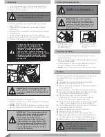
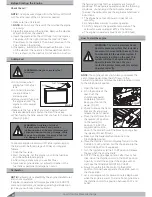
1. Transfer the gas control lever to the “START” position.
(Fig 29)
2. Put the switch key into the switch box and turn it to the
“ON” position. This will engage the electrical circuit and
in conjunction with the “START” position it will start the
engine.
NOTE:
When attempting to start a warm engine do not
set the gas control level to the “START” position.
3. DO NOT hold the key in the “START” position for longer
than ten seconds at a time. Doing so may cause damage
to your engine’s electric starter.
4. If you fail to start the engine, bring the switch key back
in the position “ON” and wait for a few seconds and then
repeat the whole procedure. If the engine will not start,
see the TROUBLE SHOOTING CHART.
5. Always ensure that the following safety precautions are
checked before you start the engine:
a. The brake is ON.
b. The blade drive is OFF.
7. Gradually reach the desired operating speed using
the accelerator and shift lever. To change the
forward speed the clutch must not be acted.
IMPORTANT:
While driving out of the lawn
the mowing mechanism must be lifted in the
highest position – position # 7.
WARNING:
The pedal has to be
released gradually as a sudden
engagement may cause tipping up and
loss of control of the vehicle.
1. Transfer the gas control lever to the “MIN” position.
2. Push down the clutch and brake pedal and then release
the hand brake.
3. Transfer the shift lever from the “N” to “L” position. If you
are not successful in transferring the shift lever from the
neutral position “N” you are to release the clutch and
brake pedal once again and repeat the procedure.
4. Proceed by changing the shift lever to the 1st speed
position.
NOTE:
Check to ensure that the segment pin is put in the
external hole of the blocking spring.
5. Slowly release the pedal which will turn from “brake” to
“clutch”, thus operating the rear wheels.
WARNING:
This machine has not been
approved for use on public roads. It has to
EHXVHGLQSULYDWHDUHDVFORVHGWRWUDI´F
IMPORTANT:
The clutch and brake pedal
operates in two various functions:
a. As a clutch. It turns the drive on or off
by releasing the belt of the drive
conversion unit.
b. As a brake. When you push the pedal
down completely.
WARNING:
Do not smoke. The fumes
from the battery acid can cause an
explosion. Keep the battery away from
DQ\µDPHVRUVSDUNV7RSUHYHQWVSDUNV
fasten the red “Jumper cable” to the
positive (+) terminal before connecting
the black “Jumper cable”.
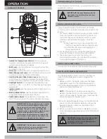
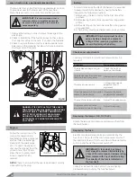
Fig 29
Cold Starting
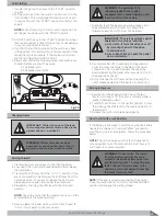
Changing Gears
Driving in Reverse
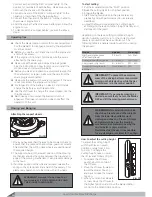
How to start with a weak battery
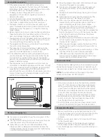
Driving Forward
NOTE:
If the seat is raised when starting the engine,
move the blade rotation control to the DISENGAGED
position and engage the parking brake.
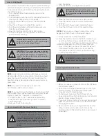
If the battery is too weak to start the engine, the battery
needs to be charged. If “Jumper Cables” are used to
start the engine in an emergency, follow the procedure
below.
NOTE:
The unit is equipped with a 12 volt negative to
ground system. Also, the other vehicle must have a 12
volt negative to ground system.
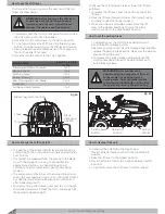
1. Reverse must be engaged ONLY when the lawn
tractor is stopped – i.e. the clutch and brake pedal is
pushed completely down.
2. Transfer the shift lever to the neutral position “N’ and
then change the shift lever to the reverse position “R”
(backwards).
3. Release the clutch and brake pedal gently.
8. Pay careful attention to gradually change gears in
order to prevent damage to the belt of the drive
conversion unit. You can decrease the speed by
slowly depressing the pedal; otherwise do not touch
the pedal while driving.
9. Do not change the shift lever without pressing the
clutch/brake pedal when the tractor is not moving.
Содержание Gizmow T130
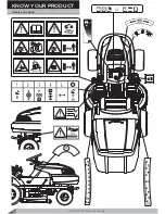
Страница 12: ...KNOW YOUR PRODUCT Lawn Tractor Rear Discharge 12 Decals and Labels ...
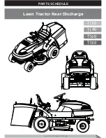
Страница 37: ...PARTS SCHEDULE Lawn Tractor Rear Discharge 37 T130 T140 T160 T180 Lawn Tractor Rear Discharge ...
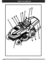
Страница 38: ...PARTS SCHEDULE Lawn Tractor Rear Discharge 38 ...
Страница 40: ...Lawn Tractor Rear Discharge 40 PARTS SCHEDULE T130 T160 T140 T180 LAWN TRACTOR 1A ...
Страница 44: ...T130 T160 T140 T180 LAWN TRACTOR 1B PARTS SCHEDULE Lawn Tractor Rear Discharge 44 ...
Страница 49: ...T130 T160 LAWN TRACTOR 1C Lawn Tractor Rear Discharge 49 PARTS SCHEDULE ...
Страница 50: ...T140 T180 LAWN TRACTOR 1C PARTS SCHEDULE Lawn Tractor Rear Discharge 50 ...
Страница 53: ...T130 T160 T140 T180 LAWN TRACTOR 1D Lawn Tractor Rear Discharge 53 PARTS SCHEDULE ...
Страница 56: ...T130 T160 T140 T180 CUTTING DECK 2 PARTS SCHEDULE Lawn Tractor Rear Discharge 56 ...
Страница 60: ...T130 T160 FRONT AXLE 7 PARTS SCHEDULE Lawn Tractor Rear Discharge 60 ...
Страница 61: ...T140 T180 FRONT AXLE 7 Lawn Tractor Rear Discharge 61 PARTS SCHEDULE ...
Страница 63: ...T130 T160 T140 T180 LIFTING LEVER 11 Lawn Tractor Rear Discharge 63 PARTS SCHEDULE ...
Страница 65: ...T130 T160 T140 T180 HUB 14 Lawn Tractor Rear Discharge 65 PARTS SCHEDULE ...
Страница 67: ...T130 T160 T140 T180 REAR AXLE 15A Lawn Tractor Rear Discharge 67 PARTS SCHEDULE ...
Страница 69: ...T130 T160 T140 T180 REAR AXLE 15B Lawn Tractor Rear Discharge 69 PARTS SCHEDULE ...
Страница 73: ...T130 T160 T140 T180 HOOD 24 Lawn Tractor Rear Discharge 73 PARTS SCHEDULE ...
Страница 75: ...T130 T160 T140 T180 PANEL 25 Lawn Tractor Rear Discharge 75 PARTS SCHEDULE ...
Страница 77: ...T130 T160 T140 T180 ELECTRICAL SYSTEM 27 Lawn Tractor Rear Discharge 77 PARTS SCHEDULE ...
Страница 78: ...T130 T160 T140 T180 ELECTRICAL SYSTEM 27a PARTS SCHEDULE Lawn Tractor Rear Discharge 78 ...
Страница 80: ...T130 T160 T140 T180 SEAT 32 PARTS SCHEDULE Lawn Tractor Rear Discharge 80 ...
Страница 82: ...T130 T160 T140 T180 BUNKER 34 PARTS SCHEDULE Lawn Tractor Rear Discharge 82 ...
Страница 84: ...T130 T160 T140 T180 GEAR SHIFTING 35 PARTS SCHEDULE Lawn Tractor Rear Discharge 84 ...
Страница 86: ...T130 T160 T140 T180 SEGMENT 36 PARTS SCHEDULE Lawn Tractor Rear Discharge 86 ...
Страница 88: ...T130 T160 T140 T180 PLATE 37 PARTS SCHEDULE Lawn Tractor Rear Discharge 88 ...
Страница 90: ...T130 T160 T140 T180 DECALS 38 PARTS SCHEDULE Lawn Tractor Rear Discharge 90 ...

