Lawn Tractor Rear Discharge
31
Switch off the lawn tractor and elevate the frame by placing
a load bearing part on the chassis which requires the wheel
to be changed.
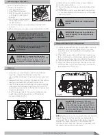
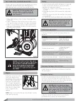
Both the front and the rear wheels are held together with
split pins. To remove the wheels, used hand pliers to
squeeze the end of the split pins and pull out the split pins
through the hole in the axle. (Fig 41)
NOTE:
If you require replacing one or both rear wheels,
check to ensure that they are of the same size (diameter).
Also check that the cutting deck is horizontal to prevent an
uneven cut.
Only make adjustment to the lawn tractor whilst it is
parked on a level ground or driveway. Ensure that the
W\UHVDUHSURSHUO\LQµDWHG
NOTE:
,IW\UHVDUHRYHURUXQGHULQµDWHG\RXZLOOQRWEH
able to properly adjust your lawn tractor mower.
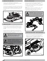
1. Check the pressure in the tyres.
2. Raise mower to its highest position.
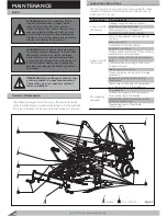
3. Adjust the adjusting screws on both sides so that
the blades tip reaches the same distance over the
ground on both sides. (Fig 43)
Reparing the tyres
Replacing the wheels
Adjusting the mower cutting height
IMPORTANT:
Apply waterproof oil on the
D[OHEHIRUHUH´WWLQJDZKHHODQGUHLQVHUW
the split pin through the axle. Once inserted,
expand the ends of the split pins to secure
the wheel.
IMPORTANT:
It is important to set the
level of the mowing mechanism to
achieve the uniformity of the cut lawn.
Split Pin
Fig 41
Fig 42
Exploded View Diagram
Wheel Assembly
If the lawn tractor is equipped with either a tube or tubeless
tyres, all puncture repairs needs to be carried out by your
authorized service centre or tyre repair expert.
Securing the steering mechanism
Check and tighten the nuts of steering mechanism once a
month.
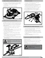
4. Measure the distance from the front of the blade tip
to the ground and rear of the blade tip to the ground.
5. For achieving the best cutting results, the front part
should always be 5 - 10 mm lower than the rear. To
achieve this distance, loosen and screw the two bolts
on each side and adjust accordingly.
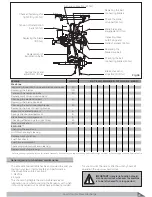
6. Adjust the height by loosening and screw the two
bolts on each side. (Fig 44)
7. Check the height again at two or three different
heights.
8. If it is not adjustable, call for your authorized service
centre.
Vertical/Height adjustment screw
Fig 43
Front and rear blade tip adjustment screws
Fig 44
Содержание Gizmow T130
Страница 12: ...KNOW YOUR PRODUCT Lawn Tractor Rear Discharge 12 Decals and Labels ...
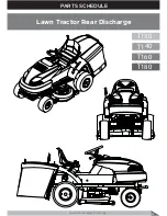
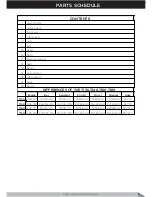
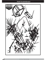
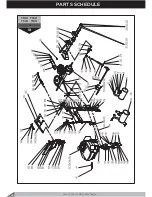
Страница 37: ...PARTS SCHEDULE Lawn Tractor Rear Discharge 37 T130 T140 T160 T180 Lawn Tractor Rear Discharge ...
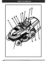
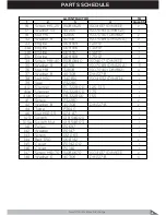
Страница 38: ...PARTS SCHEDULE Lawn Tractor Rear Discharge 38 ...
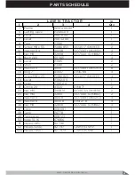
Страница 40: ...Lawn Tractor Rear Discharge 40 PARTS SCHEDULE T130 T160 T140 T180 LAWN TRACTOR 1A ...
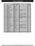
Страница 44: ...T130 T160 T140 T180 LAWN TRACTOR 1B PARTS SCHEDULE Lawn Tractor Rear Discharge 44 ...
Страница 49: ...T130 T160 LAWN TRACTOR 1C Lawn Tractor Rear Discharge 49 PARTS SCHEDULE ...
Страница 50: ...T140 T180 LAWN TRACTOR 1C PARTS SCHEDULE Lawn Tractor Rear Discharge 50 ...
Страница 53: ...T130 T160 T140 T180 LAWN TRACTOR 1D Lawn Tractor Rear Discharge 53 PARTS SCHEDULE ...
Страница 56: ...T130 T160 T140 T180 CUTTING DECK 2 PARTS SCHEDULE Lawn Tractor Rear Discharge 56 ...
Страница 60: ...T130 T160 FRONT AXLE 7 PARTS SCHEDULE Lawn Tractor Rear Discharge 60 ...
Страница 61: ...T140 T180 FRONT AXLE 7 Lawn Tractor Rear Discharge 61 PARTS SCHEDULE ...
Страница 63: ...T130 T160 T140 T180 LIFTING LEVER 11 Lawn Tractor Rear Discharge 63 PARTS SCHEDULE ...
Страница 65: ...T130 T160 T140 T180 HUB 14 Lawn Tractor Rear Discharge 65 PARTS SCHEDULE ...
Страница 67: ...T130 T160 T140 T180 REAR AXLE 15A Lawn Tractor Rear Discharge 67 PARTS SCHEDULE ...
Страница 69: ...T130 T160 T140 T180 REAR AXLE 15B Lawn Tractor Rear Discharge 69 PARTS SCHEDULE ...
Страница 73: ...T130 T160 T140 T180 HOOD 24 Lawn Tractor Rear Discharge 73 PARTS SCHEDULE ...
Страница 75: ...T130 T160 T140 T180 PANEL 25 Lawn Tractor Rear Discharge 75 PARTS SCHEDULE ...
Страница 77: ...T130 T160 T140 T180 ELECTRICAL SYSTEM 27 Lawn Tractor Rear Discharge 77 PARTS SCHEDULE ...
Страница 78: ...T130 T160 T140 T180 ELECTRICAL SYSTEM 27a PARTS SCHEDULE Lawn Tractor Rear Discharge 78 ...
Страница 80: ...T130 T160 T140 T180 SEAT 32 PARTS SCHEDULE Lawn Tractor Rear Discharge 80 ...
Страница 82: ...T130 T160 T140 T180 BUNKER 34 PARTS SCHEDULE Lawn Tractor Rear Discharge 82 ...
Страница 84: ...T130 T160 T140 T180 GEAR SHIFTING 35 PARTS SCHEDULE Lawn Tractor Rear Discharge 84 ...
Страница 86: ...T130 T160 T140 T180 SEGMENT 36 PARTS SCHEDULE Lawn Tractor Rear Discharge 86 ...
Страница 88: ...T130 T160 T140 T180 PLATE 37 PARTS SCHEDULE Lawn Tractor Rear Discharge 88 ...
Страница 90: ...T130 T160 T140 T180 DECALS 38 PARTS SCHEDULE Lawn Tractor Rear Discharge 90 ...


