Lawn Tractor Rear Discharge
15
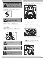
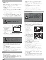
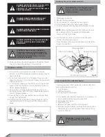
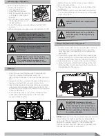
1. Fill the six battery cells with the electrolyte. (Fig 4)
2. Take off the cover (5) to other position. (Fig 5)
3. Position the battery (2) in its compartment under the
instrument board.
4. Connect the red cable to the positive (4) terminal (+) and
the black cable to the negative (1) terminal (–) using the
supplied screws.
5. Grease the connectors and pay attention to the right
location of the protective cover and its polarity.
6. Fix the battery by using the fender (3) and bolt.
7. Fit the cover (5) on and secure with the bolt (6).
3ODFHWKHODZQWUDFWRURQWKHµDWVXUIDFH
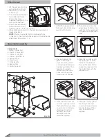
2. Position the front wheels of the lawn tractor so they are
pointing straight forward. (Fig 6)
3. Slide the steering wheel (1) onto the steering shaft
extension. (Fig 7)
4. Position steering wheel so that the cross bars are
horizontal (left to right).
NOTE:
On both the steering wheel hub and the
steering shaft extension there are locating pin holes.
Once the steering wheel has been positioned, ensure
that the locating pin hole matches the hole on the
steering shaft extension.
Fitting the steering wheel
Assemble and checking the battery
IMPORTANT:
Always fully charge the battery
according to the instructions in the battery’s
manual.
WARNING:
The battery electrolyte is
dangerous. Use work gloves and follow the
safety instructions of the battery
manufacturer.
IMPORTANT:
To prevent the safety device
in the electronics card from cutting in,
never start the engine until the battery is
fully charged!
WARNING:
Follow the battery
manufacturer's instructions regarding safe
handling and disposal.
WARNING:
Before installing the battery,
remove all metal bracelets, wrist watch
bands, rings and other metallic objects from
your hands or other areas which may get in
contact with the battery. Touching these
items to the battery could result in burns.
Fig 4
Fig 6
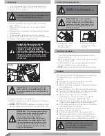
Fig 8
5. Insert the pin supplied (2) into the hole and use a
hammer to drive the pin. (Fig 8) Check to ensure that
the end comes completely through to the opposite
side.
NOTE:
To prevent damaging of the hub we
recommend driving the pin with a punch or a
screwdriver of the same diameter as the pin.
6. Pull on the steering wheel to make sure it has been
locked in place.
Fig 5
5
1
4
3
6
2
Fig 7
1
2
Содержание Gizmow T130
Страница 12: ...KNOW YOUR PRODUCT Lawn Tractor Rear Discharge 12 Decals and Labels ...
Страница 37: ...PARTS SCHEDULE Lawn Tractor Rear Discharge 37 T130 T140 T160 T180 Lawn Tractor Rear Discharge ...
Страница 38: ...PARTS SCHEDULE Lawn Tractor Rear Discharge 38 ...
Страница 40: ...Lawn Tractor Rear Discharge 40 PARTS SCHEDULE T130 T160 T140 T180 LAWN TRACTOR 1A ...
Страница 44: ...T130 T160 T140 T180 LAWN TRACTOR 1B PARTS SCHEDULE Lawn Tractor Rear Discharge 44 ...
Страница 49: ...T130 T160 LAWN TRACTOR 1C Lawn Tractor Rear Discharge 49 PARTS SCHEDULE ...
Страница 50: ...T140 T180 LAWN TRACTOR 1C PARTS SCHEDULE Lawn Tractor Rear Discharge 50 ...
Страница 53: ...T130 T160 T140 T180 LAWN TRACTOR 1D Lawn Tractor Rear Discharge 53 PARTS SCHEDULE ...
Страница 56: ...T130 T160 T140 T180 CUTTING DECK 2 PARTS SCHEDULE Lawn Tractor Rear Discharge 56 ...
Страница 60: ...T130 T160 FRONT AXLE 7 PARTS SCHEDULE Lawn Tractor Rear Discharge 60 ...
Страница 61: ...T140 T180 FRONT AXLE 7 Lawn Tractor Rear Discharge 61 PARTS SCHEDULE ...
Страница 63: ...T130 T160 T140 T180 LIFTING LEVER 11 Lawn Tractor Rear Discharge 63 PARTS SCHEDULE ...
Страница 65: ...T130 T160 T140 T180 HUB 14 Lawn Tractor Rear Discharge 65 PARTS SCHEDULE ...
Страница 67: ...T130 T160 T140 T180 REAR AXLE 15A Lawn Tractor Rear Discharge 67 PARTS SCHEDULE ...
Страница 69: ...T130 T160 T140 T180 REAR AXLE 15B Lawn Tractor Rear Discharge 69 PARTS SCHEDULE ...
Страница 73: ...T130 T160 T140 T180 HOOD 24 Lawn Tractor Rear Discharge 73 PARTS SCHEDULE ...
Страница 75: ...T130 T160 T140 T180 PANEL 25 Lawn Tractor Rear Discharge 75 PARTS SCHEDULE ...
Страница 77: ...T130 T160 T140 T180 ELECTRICAL SYSTEM 27 Lawn Tractor Rear Discharge 77 PARTS SCHEDULE ...
Страница 78: ...T130 T160 T140 T180 ELECTRICAL SYSTEM 27a PARTS SCHEDULE Lawn Tractor Rear Discharge 78 ...
Страница 80: ...T130 T160 T140 T180 SEAT 32 PARTS SCHEDULE Lawn Tractor Rear Discharge 80 ...
Страница 82: ...T130 T160 T140 T180 BUNKER 34 PARTS SCHEDULE Lawn Tractor Rear Discharge 82 ...
Страница 84: ...T130 T160 T140 T180 GEAR SHIFTING 35 PARTS SCHEDULE Lawn Tractor Rear Discharge 84 ...
Страница 86: ...T130 T160 T140 T180 SEGMENT 36 PARTS SCHEDULE Lawn Tractor Rear Discharge 86 ...
Страница 88: ...T130 T160 T140 T180 PLATE 37 PARTS SCHEDULE Lawn Tractor Rear Discharge 88 ...
Страница 90: ...T130 T160 T140 T180 DECALS 38 PARTS SCHEDULE Lawn Tractor Rear Discharge 90 ...


