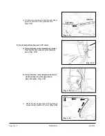
f) Route power harness from fuse-box area into
passenger-side footwell area.
(Fig. 5-6)
1. Attach wire tap connectors to B+ and +12V ignition.
a) Locate the OEM wire bundle in passenger-side
foot-well area.
(Fig. 6-1)
b)
Locate
Blue / Red-stripe wire (B+)
in bundle.
c) Using pliers, secure wire tap to
Blue / Red-stripe wire
.
(Fig. 6-1)
Fig. 5-6
6
Connect Harness Power and Ground
Fig. 6-1
Blue / Red-stripe
Wire
Green / Black-
stripe Wire
NOTE
!
Ensure Blue with RED stripe and NOT Blue with PINK stripe.
d) Locate the
Green / Black-stripe wire (+12V)
in center of bundle.
e) Using pliers, secure wire tap to
the
Green / Black-stripe wire. (Fig. 6-1)
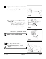
2. Connect EC power harness to ground.
10mm Bolt
Fig. 6-2
a) Locate 10mm bolt in passenger-side footwell
area as shown.
(Fig. 6-2)
b) Using 10mm socket, remove bolt.
(Fig. 6-2)
c) Place ground ring from EC power harness over
bolt and re-install bolt.
d) Tighten bolt to 80-90 in. lbs.
3. Connect EC power harness to B+ wire tap.
a) Insert male spade terminal of
solid black
Ground
Wire
Solid Black
Wire
Black /
White-stripe
Fig. 6-3
harness wire into opening of wire tap on the
Blue / Red-stripe wire. (Fig. 6-3)
4. Connect EC power harness to +12V ignition.
a) Insert male spade terminal of
black / white-stripe
harness wire into opening of wire tap on the
Green / Black-stripe wire. (Fig. 6-3)
NOTE
!
Ensure male spade connectors are fully inserted into wire taps.
Page 11 of 13
Revision A
550-0339


