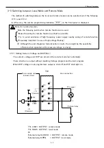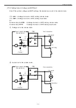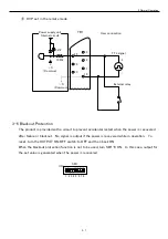
3 Normal Operation
3-4
3-4 Remote Sensing Operation
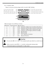
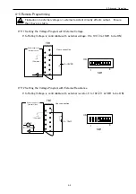
+S and –S shall be connected with output terminal (+sense→+, –sense→-) when remote
sense function is not used or when unit is connected in parallel or series.
If unit is operated wS and –S connected wit output terminal, it can cause failure.
When using the remote sense function, output cable must be connected.
(if used the remote sense function without output cable connected, there is the possibility
that large current on sense line can damage the equipment connected)
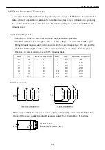
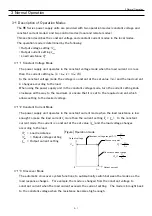
The remote sensing operation allows setting of the stabilization point of the power supply not at the
output terminal of the power supply but at the load or other points.
The loss of the lead is adjusted by 0.5 V maximum.
Use twisted or shielded wire as the lead for sensing.
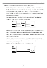
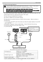
The Sense lines are provided at the Sense connector on the rear panel. Make connections as
described below:
1.
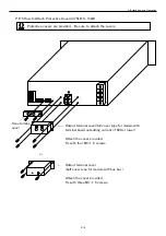
Turn the power supply OFF, wait for five minutes and remove the jumpers bS and +OUT,
and -S and -OUT.
2.
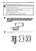
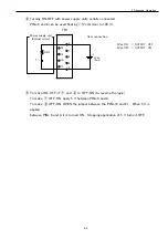
Connect the + Sense and - Sense as shown below. Connect the load in the same way.
3.
Ground the shield at one point: power supply or load.
4.
Turn the power ON.
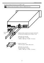
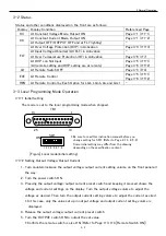
Wire and tool to be used for Sense Connector
[Figure] Remote sensing line connection
Load
+
-
-Output connector
or
-Output bus bar
-Sense line
+Sense line
Shield
-
+
+Output line
-Output line
-OUT
-S
+S
+OUT
Jumper
Jumper
Push the line inside while pressing this
part with a screwdriver.
After taking the screwdriver away, make
sure that the line does not come off by
pulling it.
Conformable wire
Single wire : φ1.0(AWG18)
Twisted wire : 0.75mm
2
Allowable range for use
Single wire : φ0.4~φ1.0(AWG26~18)
Twisted wire : 0.3mm
2
~0.75mm
2
(AWG22~20)
Wire diameter φ0.18 or larger
Standard stripping length
10mm
Tool for operating the button
Screwdriver(shaft diameter φ3, nose width 2.6)
+Output connector
or
+Output bus bar
CAUTION


