2 Installation and Operation
2-7
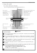
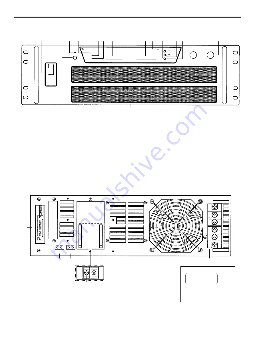
2-4-5 Front Panel(3.75kW to 15kW Type)
2-4-6 Rear Panel(3.75kW to 15kW Type)
⑩
Voltage mode indicator
⑪
Current mode indicator
⑫
Output voltage/output current preset switch
⑬
OVP setting switch
⑭
OVP setting volume
⑮
Output voltage setting volume(dial for Potentiometer at LLp option)
⑯
Output current setting volume(dial for Potentiometer at LLp option)
⑰
Vent holes
Terminals are used for output when
output current is 60A or lower.
(Bass ber for RE200-50)
①
POWER ON/OFF switch
②
OUTPUT ON/OFF switch
③
OUTPUT-ON indicator LED
④
Fault indicator
⑤
External switch OFF indicator
⑥
Remote programming indicator
⑦
Volt meter
⑧
Current meter
⑨
Remote enable indicator for GP-IB
FLT
LD
EXT
CV
CC
REN
①
② ③
④
⑤⑥
⑦
⑧
⑨⑩
⑪
⑫ ⑬
⑭
⑮
⑯
Matsusada
SET
OVP
OUTPUT
POWER
REGULATED DC POWER SUPPLY
VOLTAGE
CURRENT
V
A
⑰
①
Function setting switch
②
Connector for remote control(D-sub 25-pin)
③
Connector terminals for options
④
-Sens connector
⑤
+Sens connector
⑥
-Output bus bar
⑦
+Output bus bar
⑧
-Output terminal(M5)
⑨
+Output terminal(M5)
⑩
Exhaust
⑪
AC input terminal board
③
④
⑤
⑥
⑦
⑩
⑪
T
B
1
S
W
1
⑧ ⑨
①
②
-OUT -S +S +OUT
L1
L2
L3
Input voltage
:AC220V
200V for L(200V)
240V for L(240V)
Input phase
:3φ
Input frequency
:50/60Hz


