2 Installation and Operation
2-11
2-5 About TB1 and SW1
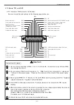
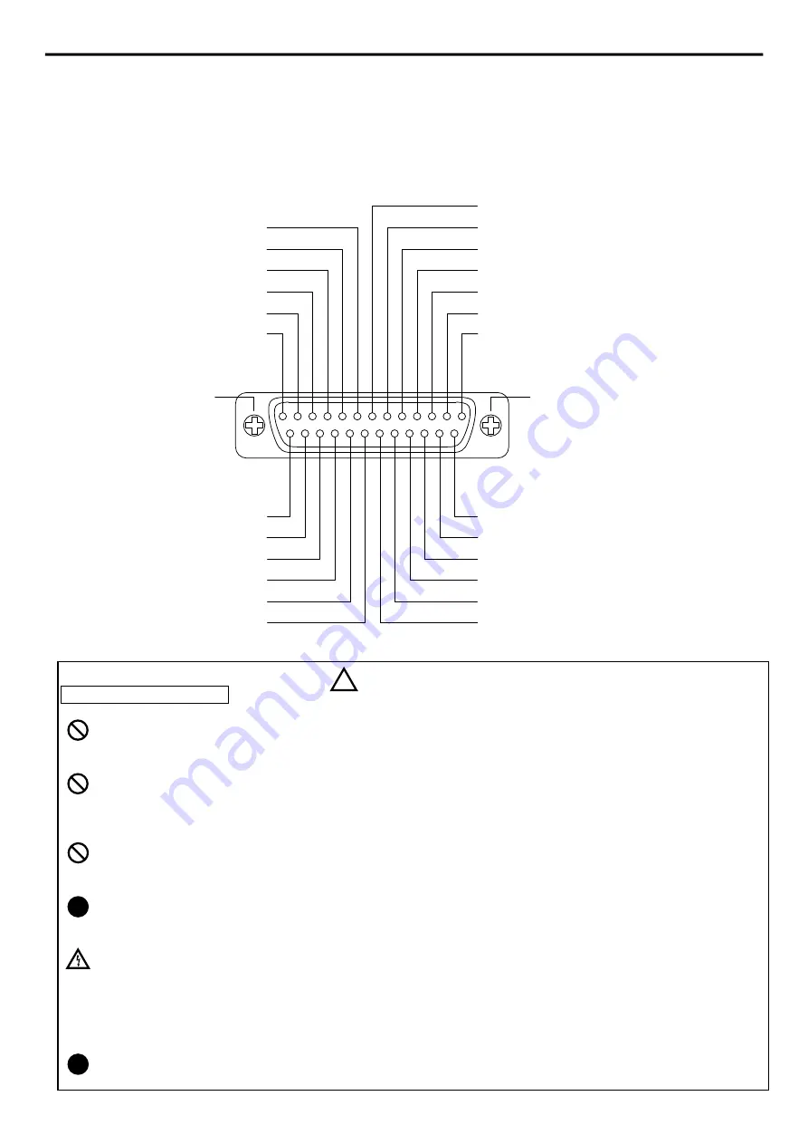
2-5-1 Contents, TB1(Connector for Remote)
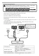
Be sure to read the instructions on the following page before use.
Instructions for safety
1.
Do not connect anything to PINs 7, 16, 17, 19, 23 and 24. Connection to any of these PINs
may damage the device.
2.
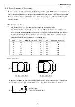
Do not connect PINs 5 and 10 directly to -S. (PINs 5 and 10 are connected to -output and
-S (Sens) in the power supply. These are the commons of the circuit of this power supply
unit.)
3.
Never ground PIN5, 10, 17 directory to the earth. When need to ground, ground the –(negative)
output.(connected to –(negative) output internally)
4.
Since PIN 5 is internally connected to -S output, devices to be connected to TB1 require
floating.
5.
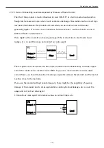
When the positive output of the power is grounded for use, voltage approximately the same as
that of the output is applied on the pins of the TB1 connector.
Use caution since this may cause a dangerous situation.
However, PINs 6, 11, 12 and 13 are insulated from the other PINs.
For details, see 4-6-2 Status Output.
6.
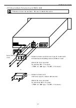
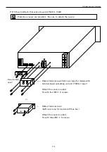
Attach the cover for D-sub connector provided before use.
Caution
!
!
MUST
NO
NO
!
MUST
CAUTION
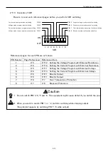
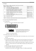
TB1
PIN
7 NC
PIN
6 External status output(CV, CC TROUBLE ) common
PIN
5 Program, monitor, reference voltage return
PIN
4 Remote switch input -
PIN
3 Output current monitor output
PIN
2 Current mode program input
PIN
1 Voltage mode program input
OVP local/remote switch
PIN25
NC
PIN24
NC
PIN23
Voltage mode local/remote switch
PIN22
Remote switch input
PIN21
Local/remote switch
PIN20
PIN14 +10.24V output(reference voltage), 4.2mA max.
PIN15 Output voltage monitor output
PIN16 NC
PIN17 NC
PIN18 OVP program input
PIN19 NC
13
1
25
14
Remote switch input +
PIN
8
Current mode local/remote switch
PIN
9
Signal system return
PIN10
TROUBLE status output
PIN11
Current mode status output
PIN12
Voltage mode status output
PIN13
(Power common connected to-S internally)
(Power common connected to-S internally)
D-Sub connector D-Sub connector
M2.6 screw M2.6 screw
NO


