3 Normal Operation
3-2
3-2 Status
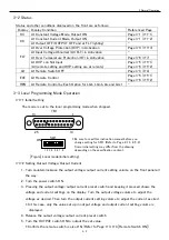
Status and other conditions displayed on the front are as follows;
Display Display Condition
Referenced Page
CV
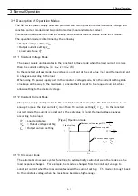
At Constant Voltage Mode, Output ON
Page 3-1 (3-1-1)
CC
At Constant Current Mode, Output ON
Page 3-1 (3-1-2)
At Output OFF (OUTPUT OFF and at FLT lighting)
-
FLT
At Over Voltage Protection (OVP) in Activation
Page 3-3 (3-3-3)
At Input Voltage Abnormal (AC FLT) in Activation
-
At Over Temperature Protection (OT) in Activation
Page 3-8 (3-7)
At OVP con Not Input
(All remote setting and OVP setting are at remote)
Page 3-5 (3-5-1)
Page 3-6 (3-5-2)
LD
At Remote Switch OFF
Page 4-3 (4-4)
EXT
At Remote Control
Page 3-5 (3-5-1)
Page 3-6 (3-5-2)
REN
At Remote Control by Each Option for LGb, LGob, LIs and LUs1
-
3-3 Local Programming Mode Operation
3-3-1 Initial Setting
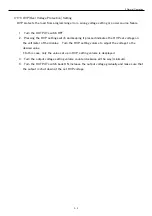
The mode is set to the local programming mode when shipped.
3-3-2 Setting Output Voltage/Output Current
1.
Turn counterclockwise the output voltage/output current setting volume on the front panel all
the way.
2.
Turn the power switch ON.
3.
Pressing the output voltage/output current preset switch and keeping it pressed shows the
voltage and current settings on the display. Turn the output voltage volume to adjust the
voltage as desired. Then turn the output current setting volume to adjust the current as sired.
* In this case, only the value set up in output voltage and output current setting volume is
displayed.
4.
Release the output voltage/output current preset switch.
5.
Turn the OUTPUT switch ON to output the set value.
* Confirm the remote switch is also ON. (Refer to Page 4-3, 4-4 [Remote Switch ON])
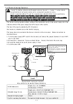
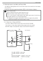
* Be sure to read this instruction manual before you
change setting for SW1. (Refer to Page 2-13, 2-5-3)
Some initial setting may differ from the drawing
depending on the specification content.
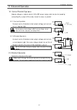
[Figure] Local mode(initial setting)
SW1
ON
1 2 3 4 5 6 7 8
TB1
13
1
25
14


