background image

Setup Guide for the RadioRA Chronos System Bridge

9

Section 1 - Getting S

tarted

System Overview

System Layout

Step 1

Determine if Bridging is Required

Bridging is required if:

• More than 32 Lighting Zone Controls exist, or
• More than 12 Master Controls exist

Step 2

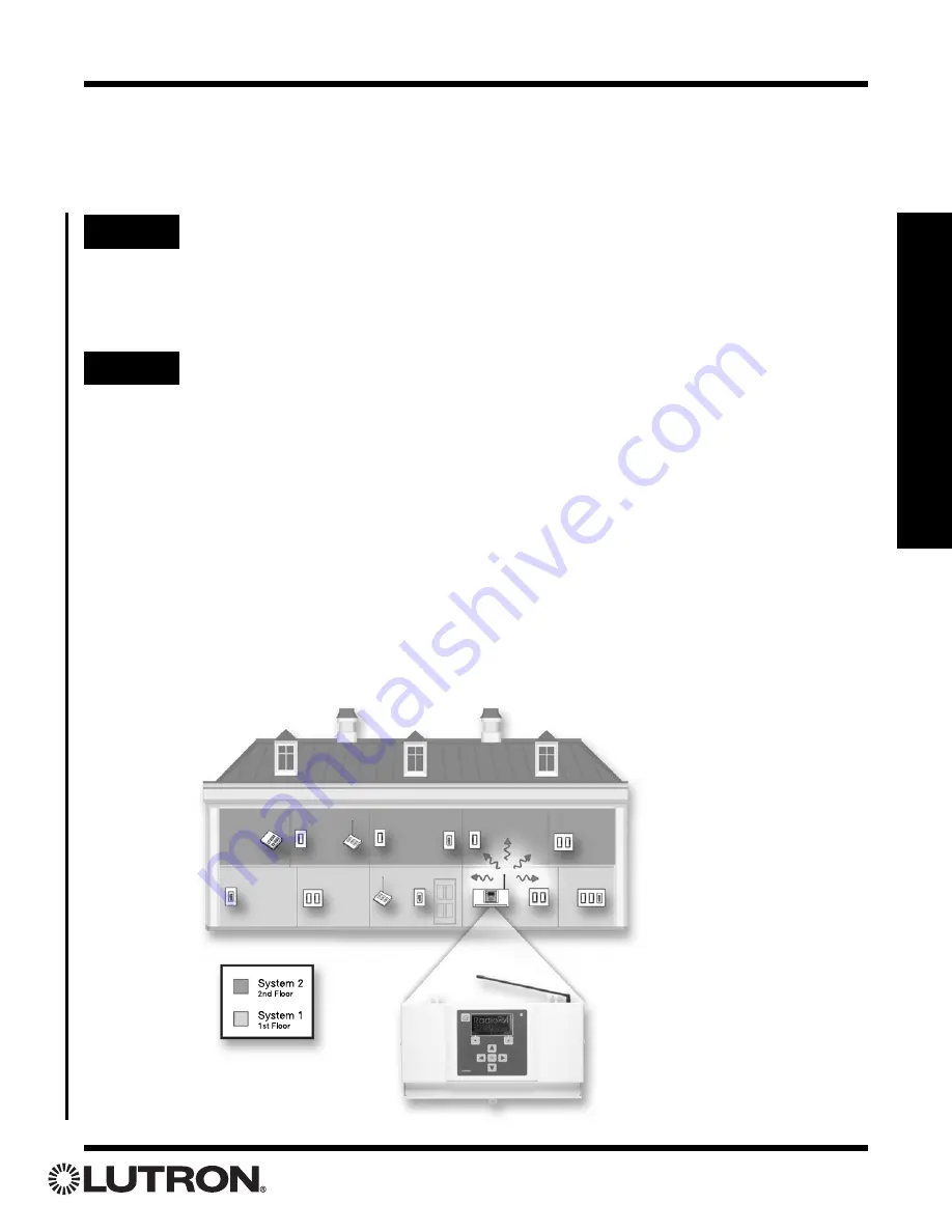
For Bridging Two Systems

For optimal light response time, devices in System 1 and System 2 should not
be used in the same room. Splitting the two systems, as shown below, is 
recommended.

Determine location of System 1 and System 2.
Examples:

a. System 1: 1st Floor

(see illustration below)

System 2: 2nd Floor

b. System 1: East Wing

System 2: West Wing

c. System 1: Interior

System 2: Exterior

Содержание RadioRA RA-SBT-CHR

Страница 1: ...Guide for Installion Programming and Operation Note Please leave this manual with homeowner RA SBT CHR RB SBT CHR Setup and Installation Guide For a RadioRA ChronosTM System Bridge and Timeclock R E...

Страница 2: ...he frequency of a RadioRA product examine the model number on the product s unit label The labels are located on the side of all wallbox products and on the bottom of all tabletop products The second...

Страница 3: ...controlled is visible from every master or local control location and that only suitable equipment is connected to this RadioRA system Using the ChronosTM System Bridge with Older RadioRA Lighting Zon...

Страница 4: ...s may not apply The figure below shows the sections containing critical information for each listed feature in the order that the sections should be read Section 1 Getting Started Section 1 Getting St...

Страница 5: ...or SCENES 28 Assigning Lighting Zone Controls to Buttons 30 Setting Light Levels GRAFIK Eye and GRAFIK RA Scene Selection for Buttons 32 Programming the ALL ON and ALL OFF Buttons 34 Advanced Local Pr...

Страница 6: ...Contact Closure Inputs 79 Section 7 User Preferences Dimmer Locked Presets Enable Dimmer Locked Presets 80 Disable Dimmer Locked Presets 82 Asymmetric Fade Rates Changing Asymmetric Fade Rates 83 Sect...

Страница 7: ...mounted Master Controls Multi function Entry Master Control and Visor Control Transmitter Tabletop Master Controls System Interface Master Controls RS 232 Switch Closures and Infrared IR RF Signal Rep...

Страница 8: ...ese events can be scheduled relative to sunrise sunset or time of day Contact Closure Inputs One security and two general purpose contact closure inputs allow interfacing to security and other third p...

Страница 9: ...More than 12 Master Controls exist Step 2 For Bridging Two Systems For optimal light response time devices in System 1 and System 2 should not be used in the same room Splitting the two systems as sho...

Страница 10: ...ers within 60 feet 18 m of each other Place System 2 Repeaters within 60 feet 18 m of each other Chronos System Bridge Place the Chronos System Bridge within 60 feet 18 m of a Repeater in each system...

Страница 11: ...tion listed in the bottom right corner of the LCD 8 Navigation Buttons For navigating menus and changing settings 9 RS 232 Activity LEDs Indicate when RS 232 communications are present 10 RS 232 Port...

Страница 12: ...e Chronos System Bridge in a metal enclosure 6 Do not paint the Chronos System Bridge 7 The range and performance of the RadioRA System is highly dependent on a variety of com plex factors such as Dis...

Страница 13: ...ions contact the manufacturer of that device Contact Closure Wiring Caution DO NOT apply voltage between any two terminals on the Chronos System Bridge contact clo sure input terminal block This will...

Страница 14: ...ED above the power jack labeled PWR IN is not on when powered ensure that the AC adapter is installed prop erly and that there is power at the receptacle If problem persists call the Lutron Technical...

Страница 15: ...try There are 2 basic types of screens used for data entry On single row edit screens the and buttons are used to move from one data field to another The and buttons are used to change the value of th...

Страница 16: ...o the Chronos System Bridge for navigation and data entry The keys on the keyboard are used as follows Keyboard Key Chronos Button Function Change value or move to next or previous item Accept selecti...

Страница 17: ...all devices of an existing RadioRA system must be reset to the factory default settings and reprogrammed System Maximums System Configuration and Features Available System Bridge Chronos System Bridge...

Страница 18: ...ote In order to bridge systems Main Repeater must be set to Yes The Chronos System Bridge will automatically set Main Repeater to Yes when Bridge Systems is set to Yes Bridge Systems Set this value to...

Страница 19: ...urns on approxi mately 3 seconds The green ACTIVATE CONTROLS LED on ALL Repeaters will turn ON Press OK to activate the Chronos System Bridge Once the Chronos System Bridge has com pleted initializati...

Страница 20: ...hen Repeater has been activated System Setup Activate Aux Repeaters Activate Controls Address Usage Diagnostics Back Help Activate Aux Repeaters Begin Activating Aux Repeaters in System 1 Auxiliary Re...

Страница 21: ...5 Complete Repeater activation Press Done button on the ChronosTM System Bridge The green ACTIVATE REPEATER LED on ALL auxiliary repeaters will turn off The AUXILIARY LED will remain on Repeater acti...

Страница 22: ...ese numbers will update as new Zone Controls and Master Controls are activated The green ACTIVATE CONTROLS LED on ALL auxiliary repeaters will turn ON Activate Controls Begin Activating Controls in Sy...

Страница 23: ...will increment by one Activate one Lighting Zone Control at a time Wait for the control to flash its light s before activating any remaining controls Repeat Step 4 to activate any remaining Lighting Z...

Страница 24: ...set Flash to No OR press and hold the FLASH button on any Repeater until the green FLASH LED turns off approximately 3 seconds If any Master Control or Lighting Zone Control has not been activated re...

Страница 25: ...ENE Buttons also assign all Lighting Zone Controls that will be turned OFF by the button being programmed b Set Light Levels Lighting Zone Controls assigned to each button may be set to desired light...

Страница 26: ...off because all of the lights in the Room are OFF Our two SCENE buttons TV and Movie are off because the lights are not at the pre selected levels for those SCENES Pressing the Family button turns ON...

Страница 27: ...Phantom Buttons A Phantom Button is a virtual button that resides in the ChronosTM System Bridge and is used to activate light ing in a single system or both systems Any or all zones of lighting with...

Страница 28: ...fer to page 25 Changing a column assignment from ROOM to SCENE or vice versa will delete all previous programming in that column of buttons If the first LED in a column is flashing the buttons in that...

Страница 29: ...e right most column until the LEDs stop flashing approximately 3 seconds Note On a 5 button Raise Lower Wall Master press and hold the 3rd 5th and Lower but tons Step 4 Label columns Apply the supplie...

Страница 30: ...RATM Control Unit to the Master Control button by pressing one of the GRAFIK Eye GRAFIK RA Control Unit scene buttons Assign all GRAFIK Eye GRAFIK RA Control Units to be affected by this button For SC...

Страница 31: ...aster Control have been programmed Repeat Steps 1 through 5 for any additional Master Controls Proceed to Setting Light Levels GRAFIK Eye Scene Selection for Local Buttons on page 32 Repeat Steps 2 an...

Страница 32: ...Dimmers and Switches Go to any assigned Dimmer Adjust this Dimmer s programmed light level for the selected button using the dimming rocker For SCENE Buttons turn the Dimmer OFF if it is to be turned...

Страница 33: ...Local Button Programming on page 36 Proceed to Step 6 when all buttons on this Master Control have been programmed Simultaneously press and hold the 1st and 5th buttons in the right most column until...

Страница 34: ...trol programming process refer to page 25 Step 2 Select a button On the Master Control to be programmed simultaneously press and hold the 2nd and 4th buttons in the right most column until the upper r...

Страница 35: ...onds Turn OFF the Lighting Zone Control s that are to be removed from the ALL ON or ALL OFF button being programmed Dimmer If the wrong Lighting Zone Control is removed from the ALL ON or ALL OFF butt...

Страница 36: ...and 5th buttons in the right most column until the upper right LED begins to blink approximately 3 seconds Press and release the button to be pro grammed Its LED will begin to blink Note To copy to a...

Страница 37: ...olumn until all LEDs begin to flutter approximately 3 seconds Repeat Steps 2 and 3 for all Master Control but tons to copy programming to When the LED turns off for a few seconds and then resumes flas...

Страница 38: ...al Programming Step 1 Begin Erasing Button Programming Simultaneously press the 2nd and 4th buttons in the right most column until the upper right LED begins to flash approximately 3 sec onds Step 2 S...

Страница 39: ...column until all LEDs begin to flutter approximately 3 seconds The LED will stop fluttering and begin to flash All Lighting Zone Controls will turn off and programming is now erased from that Master...

Страница 40: ...ure does not apply Whole home Phantom Button Programming Step 1 Go to Phantom Button Setup If bridging two systems Main Menu Whole home Button Setup Phantom Button Setup If not bridging systems Main M...

Страница 41: ...SC Use the and buttons to highlight a Phantom Button Press Select button to change select ed button from ROOM to SCENE or SCENE to ROOM Note Changing the button type will erase any pro gramming curre...

Страница 42: ...to Assign 1 RM Home 2 RM Btn 2 3 RM Btn 3 4 RM Btn 4 Exit Select Assign Zones Entering Assignment Mode Assign Zones Turn on devices to be assigned to Home Continue Copy Button Step 2 Assign Zones Step...

Страница 43: ...r of the screen The arrow on the right of the screen indicates which Phantom Button is currently in Assignment Mode Use the and buttons to select a Phantom Button Press Select button to enter Assignme...

Страница 44: ...enter Level Set Mode for the highlighted button The following screen will be dis played while Level Set Mode is initiated Once Level Set Mode has been initiated the following screen will be displayed...

Страница 45: ...l Unit if it is to be turned OFF when the Phantom Button is activated Step 5 Select next Phantom Button Press Continue button to display the list of Phantom Buttons Note The system is still in Level S...

Страница 46: ...itches or GRAFIK Eye Interfaces that were manufac tured prior to January 1 2001 the Legacy setting MUST be used Select Btn to Set Properties 1 RM Home 2 RM Btn 2 3 RM Btn 3 4 RM Btn 4 Back Select Set...

Страница 47: ...scenes Also this feature was not supported in RA RS232 and RA IR Interfaces shipped prior to September 1 2001 For this reason these older devices cannot be used to activate Whole home scenes Whole ho...

Страница 48: ...n Press Cancel button to cancel the erase operation Note Erasing Button 16 All On or Button 17 All Off will reassign ALL zones to that button Step 3 Erase Phantom Button If bridging two systems Main M...

Страница 49: ...button or scene to be copied to Press Select button to enter Zone Assignment Mode or Level Set Mode for the button scene selected Assign Zones Turn on devices to be assigned to Morning Copy Button Co...

Страница 50: ...r scene to copy to Use and to highlight the button or scene to be copied to Press Select button to enter Zone Assignment Mode or Level Set Mode for the button scene selected Assign Zones Turn on devic...

Страница 51: ...CCI Scenes Master Control Back Select Step 6 Select the Master Control but ton to copy from All LEDs on Master Controls will be blinking Press and hold the Master Contol button to be copied from unti...

Страница 52: ...ings Menu select Date Use and to change the selected field Use and to highlight the next previous field To cancel the changes press Cancel button To accept the changes press Done button Date 06 17 200...

Страница 53: ...a South Carolina South Dakota Select City Philadelphia Previous Next Coopersburg Pittsburgh State College Astronomical Time Clock Programming Step 6a Set Location by State and City Step 6b Set Locatio...

Страница 54: ...Programming Astronomical Time Clock Programming Step 9 Set Time Format From Time Date Settings select Time Format Use and to change between 12 and 24 hour format To cancel the changes press Cancel but...

Страница 55: ...ene to Name 1 Scene 1 2 Scene 2 3 Scene 3 4 Scene 4 Back Select Step 2 Set the Scene Names Set Name Name _ _ _ _ _ _ _ _ Cancel Done M o r n i n g Step 3 Assign Zones From Manage Scenes select Assign...

Страница 56: ...ign Zones 1 Morning 2 Scene 2 3 Scene 3 4 Scene 4 Exit Select Assign Dimmers or Switches to the selected Time Clock Scene by turning the Controls ON Assign all Dimmers and Switches to be affect ed by...

Страница 57: ...ls Entering Level Set Mode Set Zone Levels Set light levels for devices assigned to Morning Continue Copy Button Step 7 Set light levels and GRAFIK Eye GRAFIK RATM Scenes Use the dimming rocker to adj...

Страница 58: ...corner of the screen The arrow on the right of the screen indicates which scene is currently in Level Set Mode Use and buttons to highlight a new Time Clock scene Press Select button to enter Level Se...

Страница 59: ...current state is displayed Use and to select a scene Press Toggle button to toggle the scene ON and OFF Repeat for all Time Clock Scenes to be tested Press Back button to return to Manage Scenes Test...

Страница 60: ...l Time Clock Programming Select Scene to Erase 1 Morning 2 Scene 2 3 Scene 3 4 Scene 4 Back Select Are you sure Erase Morning Cancel Yes Note Erasing a Time Clock Scene will erase both the name and al...

Страница 61: ...ent occurs every day Step 4 Set Event Time There are three types of Time Clock events Fixed Time Sunrise Sunset Fixed Time events are events that will activate at a specific time The Time field is use...

Страница 62: ...s Away Note The activation time for an Away event will vary in order to make the residence appear lived in The Away event will activate within 20 minutes of the scheduled time Fade Time determines the...

Страница 63: ...SS 1 00 Porch Done Details View Modify Event Name Time Sunrise 1 35Hr Schedule All Days Scene Morning Back Change Wakeup Use and to highlight the desired setting Press Back button to return to the eve...

Страница 64: ...gramming Step 2 Delete an Event Use and to highlight an event Press Back button to return to Manage Timed Events Press Delete button to delete the selected event Press Yes button to confirm deleting t...

Страница 65: ...Setup Press Done button to accept the mode setting The Time Clock Home Away Mode can also be changed from the Chronos Status screen This screen is accessed by pressing Home Button from the Home Scree...

Страница 66: ...e an external device Individually control a zone React when a zone is changed locally Master Control Numbers must be assigned to have an external device React when a Master Control button is pressed C...

Страница 67: ...especial ly with a laptop use 9600 baud Flow Control None Hardware Turning hardware flow control ON is recommended for maximum reliability Prompt ON OFF Turn ON or OFF the prompt that is issued when t...

Страница 68: ...each system Device Number Setup will appear as below Use and to highlight the system and press OK to proceed to the next step Device Number Setup System 1 Device Numbers Back Help System 2 Device Numb...

Страница 69: ...Continue button to continue assigning Zone Numbers Repeat Steps 2 and 3 for any remaining Zone Numbers to be assigned Press Done button to return to Device Number Setup Zone Numbers are now assigned P...

Страница 70: ...each system Device Number Setup will appear as below Use and to highlight the system and press OK to proceed to the next step Device Number Setup System 1 Device Numbers Back Help System 2 Device Numb...

Страница 71: ...assigned the screen will change to Press Continue button to continue assigning Control Numbers Repeat steps 2 and 3 for any remaining Control Numbers to be assigned Press Done button to return to Devi...

Страница 72: ...n Setup From Whole home Button Setup select Phantom Button Setup Refer to pages 40 48 for details on Phantom Button Programming If the Chronos System Bridge is not con figured to bridge systems From t...

Страница 73: ...type is not already set to Scene CCI 1 Setup Set Type Closure Settings Scene Back Help Assign Zones Set Zone Levels Step 3 Setup Closure Settings From CCI 1 or CCI 2 Setup select Closure Settings Use...

Страница 74: ...ssigned to the CCI OR use the toggle button to turn Dimmers or Switches OFF if they are to be turned OFF when the CCI is activated Contact Closure Programming Assign Dimmers or Switches to the CCI by...

Страница 75: ...minute 4 minutes and Legacy If the system contains Dimmers Switches or GRAFIK Eye Interfaces that were manufactured prior to January 1 2001 the Legacy setting MUST be used Switches determines whether...

Страница 76: ...Contact Closure Setup From Contact Closure Setup select either CCI 1 or CCI 2 Step 2 Setup Contact Closure Type CCI 2 Setup Set Type Closure Settings Clock Mode Back Help Test CCI Use and to set the...

Страница 77: ...is exited contact closure is released system controls resume normal operation Follow the procedure below to program which lights will turn on to Full and which lights will Flash Step 1 Go to Security...

Страница 78: ...Unit by selecting a GRAFIK Eye GRAFIK RA scene If the wrong Lighting Zone Control is assigned to Security Flash turn the Lighting Zone Control OFF to unassign it Press Continue button to return to Sec...

Страница 79: ...act Closure Setup select CCI 1 Setup CCI 2 Setup or Security Setup Step 2 Enter Test Mode CCI 2 Setup Assign Zones Set Zone Levels Back Help Set Properties Test CCI Test CCI 2 CCI 2 State Open CCI 2 S...

Страница 80: ...te Enabling or Disabling Locked Presets will affect all dimmers with the push in pull out FASS in all systems affected by the Chronos System Bridge Dimmer Locked Presets Main Menu User Preferences Dim...

Страница 81: ...ecting No will not allow any local changes Once Yes or No is selected press Next but ton to continue Press Previous button to return to the previous screen Press Yes button to confirm enabling Locked...

Страница 82: ...Locked Presets Press Next button to disable Locked Presets Press Previous button to cancel the disable operation Press Yes button to confirm disabling Locked Presets Press Previous button to return t...

Страница 83: ...e ChronosTM System Bridge Note Enabling or Disabling Asymmetric Fade Rates will affect all dimmers with the push in pull out FASS in all systems affected by the Chronos System Bridge Asymmetric Fade R...

Страница 84: ...rols have been awak ened press Requery button to query the sys tem again If all devices are accounted for pressing Continue button will return to Address Usage If all devices are not accounted for pre...

Страница 85: ...ng device from the system The follow ing screen will be displayed Press Yes button to delete the selected Control Press Cancel button to cancel the delete operation Note Deleting a Control will comple...

Страница 86: ...ayed only if the button type is Linked Phantom N where N is the Whole home Phantom Button that the Master Control Button is linked to Zone Controls Type Zone Control System 1 2 or Unaddressed Address...

Страница 87: ...turns ON approximately 3 seconds Main Menu System Setup Diagnostics Use to highlight Flash Mode Use to set Flash Mode to Yes Diagnostics Flash Mode Yes Beep Mode No System Beep Mode No Back Help Gree...

Страница 88: ...fter checking all Controls press and hold the FLASH button on any Repeater until the green FLASH LED turns OFF approximately 3 seconds From a Repeater From the ChronosTM System Bridge as a Main Repeat...

Страница 89: ...LED turns ON approximately 3 sec onds Green BEEP LED on that Repeater only will be ON From the Chronos System Bridge as a Main Repeater only Main Menu System Setup Diagnostics Use to highlight Beep Mo...

Страница 90: ...LED will stay ON Press and hold the BEEP button on the Repeater you are checking until the green BEEP LED turns OFF approximately 3 sec onds From a Repeater From the ChronosTM System Bridge as a Main...

Страница 91: ...ighlight System Beep Mode Use to set System Beep Mode to Yes Diagnostics Flash Mode No Beep Mode No System Beep Mode Yes Back Help Step 2 Check a Control Turn the Lighting Zone Control ON or OFF press...

Страница 92: ...When the Power LED stays ON the unit is ready for operation Activating a Switch Closure Input Interface RS 232 Interface or Infrared IR Interface From the ChronosTM System Bridge as a Main Repeater on...

Страница 93: ...main on The Interface is now activated To program the input channels on the Switch Closure Input Interface refer to the RadioRA Setup Guide P N 044 001 The green ACTIVATE CONTROLS LED on ALL Repeaters...

Страница 94: ...not do this unless you are sure that it is necessary For more information call the Lutron Technical Support Center Step 1 Begin returning to Default Factory Settings Step 2 Complete returning to Defa...

Страница 95: ...rning Components to Default Factory Settings Step 1 Turn FASSTM switch OFF Move the Front Accessible Service Switch FASS to the OFF position or unplug Dimmer if it is a Lamp Dimmer If the LEDs chase d...

Страница 96: ...The light the Switch controls will turn ON and OFF a few times indicating that the Switch was returned to Default Factory Settings Release and then press and hold the paddle switch for 2 seconds Move...

Страница 97: ...tion Do not do this unless you are sure that it is necessary For more information call the Lutron Technical Support Center Step 1 Remove faceplate Step 2 Return to Default Factory Settings Press and h...

Страница 98: ...ATER LED or ACTIVATE CONTROLS LED on any Repeater is NOT ON before pro ceeding If either LED is ON press the corre sponding button until it s LED turns OFF approximately 3 seconds Returning Components...

Страница 99: ...Settings will permanently delete all current pro gramming information Do not do this unless you are sure that it is necessary For more information call the Lutron Technical Support Center Step 1 Begi...

Страница 100: ...ntly delete all current program ming information Do not do this unless you are sure that it is necessary For more information call the Lutron Technical Support Center Step 1 Begin Returning to Default...

Страница 101: ...delete all current programming information Do not do this unless you are sure that it is necessary For more information call the Lutron Technical Support Center Step 1 Begin Returning to Default Fact...

Страница 102: ...ttons for approximately 4 seconds Do not release the buttons The following screen will appear Are you sure Return to default Cancel Yes factory settings Step 2 Complete Returning to Default Factory Se...

Страница 103: ...trol SCENE LEDs which have that Dimmer assigned to them will turn OFF since the lights are no longer at their preset level for that SCENE System Functionality The Raise Lower buttons are designed to w...

Страница 104: ...s they work very similarly to LEDs on RadioRA Master Controls Phantom LEDs 1 15 are associated with Phantom Buttons 1 15 respectively ROOM Button A ROOM button is a programmable button whose LED is ON...

Страница 105: ...urns ON and then back OFF when attempting to go into ACTIVATE CONTROLS mode After activating a Dimmer Switch or GRAFIK Eye Control Unit the control changes state but does not flash the light s it cont...

Страница 106: ...ease call the Lutron Technical Support Center Move the Switch Closure Interface closer to a System Repeater Place system in ACTIVATE CONTROLS mode VIII IX Burned out or missing light bulb Front Access...

Страница 107: ...contains Dimmers shipped prior to January 1 2001 Button already has local program ming on it External Control is not enabled on the Master Control Master Control was shipped prior to January 1 2001 C...

Страница 108: ...e action is set to Scene On from the Manage Events menu Check the Time Clock Mode from the Chronos Status screen Verify this match es the type for the event from the Manage Events menu XIV XV Dimmer S...

Страница 109: ...Setup Guide for the RadioRA Chronos System Bridge 109 Notes...

Страница 110: ...states do not allow the exclusion or limitation of incidental or consequential damages or limitation on how long an implied warranty may last so the above limitations may not apply to you This product...

Отзывы: