


Chapter 11. Monitoring
11-1
11.
Monitoring
11.1
Operating
Status
Monitoring
z
Output current
Group
Code Parameter Name
Setting
Range
Initial
Unit
Drive Group
CUr
Output current
-
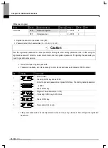
Inverter output current can be monitored in CUr code.
z
Motor RPM
Group
Code Parameter Name
Setting
Range
Initial
Unit
Drive Group
rPM
Motor RPM
-
P41
No. of motor poles
-
2 ~ 12
4
P46
Control mode select
-
0 ~ 2
0
PG Group
P54
Gain for motor rpm display
-
1 ~ 1000
100
%
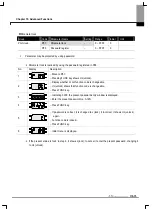
Motor rpm can be monitored in rpm code of Drive Group.
When P46 is set to 0(V/F control) or 1(PID control), the Inverter output frequency (f) is displayed in RPM
using the formula below without Motor slip considered.
P41: Enter the number of rated motor poles on the nameplate.
P54: Enter gear ratio to monitor mechanical rotation, instead of rotation of motor axis.
z
Inverter DC link voltage
Group
Code Parameter Name
Setting
Range
Initial
Unit
Drive Group
dCL
Inverter DC link voltage
-
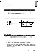
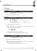
Inverter DC link of input voltage can be monitored in dCL.
2
times (1.414) the value of input voltage is displayed while motor is at a stop. This is why it is converted
to DC voltage, the maximum of AC voltage by a rectifier.
It is the voltage between P1 on the inverter’s power terminal and N terminal.
100
54
41
120
P
P
f
RPM
×
⎟
⎠
⎞
⎜
⎝
⎛
×
=
Содержание SV-iE5 Series
Страница 124: ...iV ...