


Chapter 3. Wiring
3-1
3.
Wiring
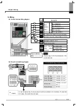
3.1
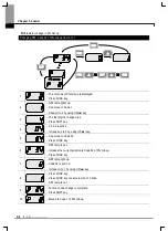
Control Terminal Wiring Diagram
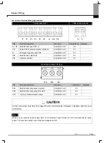
3.2
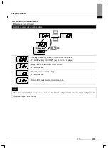
Power Terminal Wiring Diagram
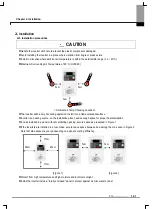
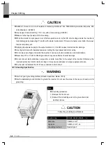
Caution
In case of single phase, the input power should be connected to R, S terminals. If connected
to T phase, the inverter does not work.
Note
Refer to page 3-3 for the dimensions of the
control terminal
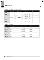
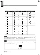
0.1~0.4kW IE5 Power Terminal Spec.
I wire thickness
16AWG, 1.25 mm
2
O wire thickness
16AWG, 1.25 mm
2
G wire thickness
14AWG, 1.25 mm
2
I/O terminal
16AWG, 1.25 mm
2
/3.5
φ
Terminal torque
3.5 lb-in
220Vac
U V W
P P1 DCN
R S T
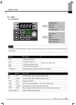
30A
30B
30C
A contact output
B contact output
A/B contact common
Multi function
relay output
terminal
Multi
function
Input
terminal
Input signal common
12V power(12V,100mA) for external volume
Def
au
lt
FX : forward run
RX : reverse run
EST : emergency stop
JOG : jog operation
RST : trip reset
Analogue frequency input(Voltage or current)
Analogue output: 0 ~ 10V
P1
P2
P3
P4
P5
CM
VR
AM
AI
G
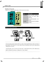
Power-indicative
lamp
Description
T/M
Содержание SV-iE5 Series
Страница 124: ...iV ...