


4D-Nucleofector™ Manual –
Bioscience Solutions
9
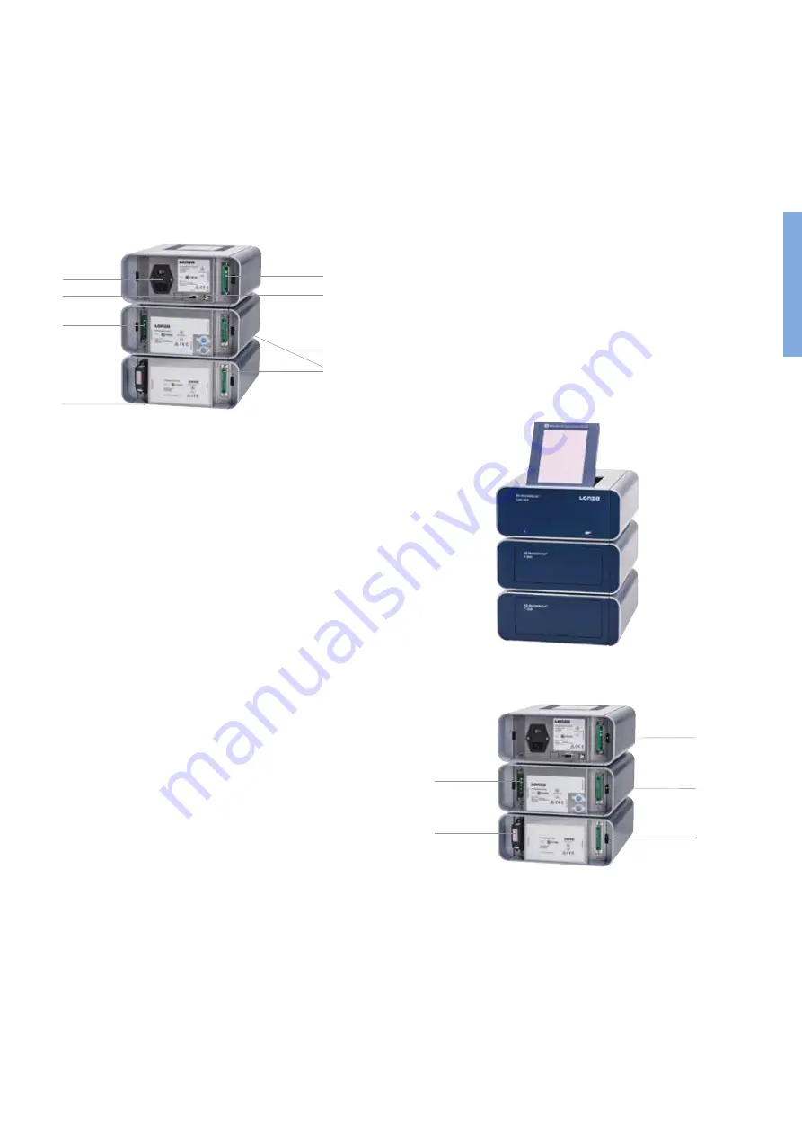
11. Power cord socket with main power switch and fuses
12. USB port (for PC connection)
13. Serial port for shuttle connection
14. Lonza interface outlet port to connect functional units
15. Lonza interface inlet port to connect functional units
16. Lonza interface inlet port of last functional unit with
termination plug
17. HV outlets for the 96-well Shuttle™ Add-on
Figure 2.3:
4D-Nucleofector™ System comprising Core, X and Y Unit (rear view)
14
13
15
11
14
12
17
The 4D-Nucleofector™ System comes with default programs and includes
a USB port at the front for software updates.
16
2.6 Set-up Instructions
1. Unpack the components of the 4D-Nucleofector™ System and check
for completeness.
2. Stack the units with the Core Unit (containing the touch screen) on
top (figure 2.4)
3. Connect the units (figure 2.5) by using the interface cables:
– Connect the interface outlet port of the Core Unit (A) with the
interface inlet port of the first functional unit (X or Y Unit; B). Make
sure that the cable is securely attached and that the retaining
screws on the cable housing are screwed tightly into the port.
– Further functional units are added by connecting the outlet (C)
and the inlet port (D) of adjacent units as described above.
–
Important:
Plug in the interface terminator cap into the outlet of
the last unit (C or E).
4. Attach the power cord to the power cord socket at the rear side of the
Core Unit and plug it into an appropriate power outlet.
5. Check all connections before turning on the system for the first time.
Figure 2.4:
Stacked units
Figure 2.5:
Inlets and outlet ports for unit connection
A
B
E
C
D
2


