Smart Process Gating
Leuze electronic GmbH + Co. KG
MLC 530 SPG
22
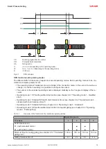
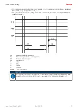
• If necessary, the controlled gating end must be used to shorten the gap (see chapter 4.5.1 "Con-
• If no other measures are possible, a hard guard is to be extended accordingly.
NOTICE
Erroneous operation when generating the CS switching signal!
If the generation of the CS switching signal is directly and solely dependent on the action of a
person, deliberate misuse or tampering are possible.
Ä
Make certain that the CS switching signal is never directly derived or derived solely from the
pressing of a button.
This applies, in particular, for SPG operation at picking stations.
NOTICE
Ä
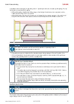
The limits of 200 mm before and after the danger zone must also be maintained on system
start-up or in the event of changed conveyor speeds.
In accordance with the risk assessment or machine-specific C-standard, deviations may be
possible under certain circumstances.
Ä
Adherence to the limits of 200 mm before and after the danger zone must be taken into con-
sideration in the system design.
Defining the operating mode
Ä
Depending on the function required, select the suitable operating mode via corresponding electrical
wiring (see chapter 8 "Electrical connection").
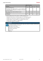
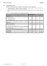
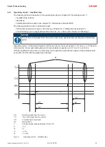
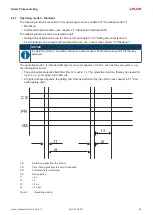
see chapter 4.4.1 "Operating mode 1 - Qualified stop"
see chapter 4.4.2 "Operating mode 4 - standard with short tolerance times"
see chapter 4.4.3 "Operating mode 5 - Standard"
see chapter 4.4.4 "Operating mode 6 - Partial gating"
Ending gating
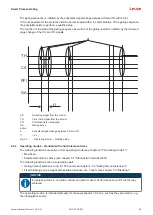
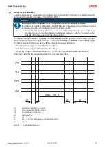
• Automatic gating end: The protective field is clear for longer than 0.5 s (operating mode 4), 1 s (operat-
ing mode 5) or 2 s (operating mode 1 or 6).
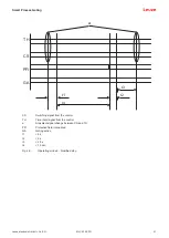
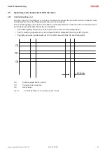
• Controlled gating end: The signals from the protective field and CS switching signal are both inactive
for longer than 0.1 s (see chapter 4.5.1 "Controlled gating end").

