


Device description
Leuze electronic GmbH + Co. KG
MLC 530 SPG
16
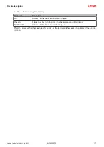
LED
Color
State
Description
3
Blue
OFF
No special function (blanking,
SPG, …) active
ON
Protective field parameter (blank-
ing) correctly taught
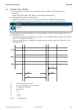
Slowly flashing
• SPG active
• or override active
Short flashing
Protective field interrupted and
RES blocked
• Teaching of protective field pa-
rameters
• or restart/override necessary
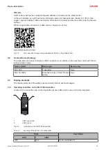
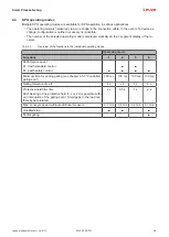
7‑segment display
In normal operation, the 7-segment display shows the number of the operating mode. In addition, it helps
during the detailed error diagnostics (see chapter 12 "Troubleshooting") and serves as an alignment aid
(see chapter 9.2 "Aligning the sensor").
Tab. 3.4:
Meaning of the 7-segment display
Display
Description
After switching on
8
Self test
t n n
Response time (t) of the receiver in milliseconds (n n)
In normal operation
1, 4, 5 or 6
Selected operating mode
1, 4, 5 or 6 flashing
Weak signal
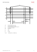
For alignment
Alignment display (see chapter 3.3.3 "Alignment display").
• Segment 1: beam area in upper third of the protective field
• Segment 2: beam area in middle third of the protective field
• Segment 3: beam area in lower third of the protective field
For error diagnostics
F…
F
ailure, internal device error
E…
E
rror, external error
U…
U
sage info, application error
For error diagnostics, the error's respective letter is displayed first followed by the number code. The dis-
play is repeated cyclically. In the case of blocking errors, the voltage supply must be separated and the
cause of the error must be eliminated. Before switching on again, the steps taken before initial commission-
ing must be repeated (see chapter 10.1 "Before commissioning and following modifications").
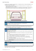
The 7-segment display switches to alignment mode when the device has not yet been aligned or when the
protective field has been interrupted (after 5 s). In this case, a fixed beam area from the protective field is
assigned to every segment.
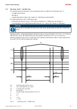
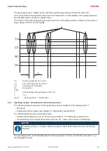
3.3.3
Alignment display
Approximately 5 s after a protective-field interruption, the 7-segment display switches to alignment mode.
In this mode, one third of the total protective field (top, middle, bottom) is assigned to one of the three hori-
zontal segments. In the case of uniform resolution over the entire protected area, the state of this partial
protective field is indicated as follows:


