Smart Process Gating
Leuze electronic GmbH + Co. KG
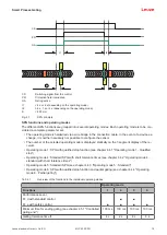
MLC 530 SPG
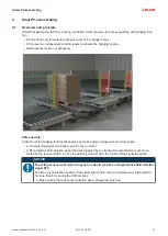
19
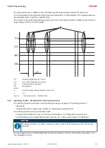
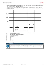
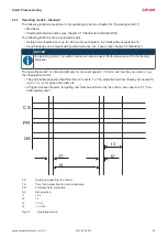
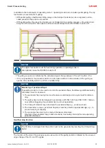
CS
PFI
GA
t1
t2
D
D
CS
Switching signal from the control
PFI
Protective field interrupted
GA
Gating active
t1
< 4 s or 2 s (depending on the operating mode)
t2
0.5 s, 1 s or 2 s (depending on the operating mode)
D
< 200 mm
Fig. 4.1:
SPG principle
SPG functions and operating modes
The different SPG functions are grouped into several operating modes. Each operating mode is to be con-
sidered a complete parameter set.
• The operating mode is hardwired via a wire bridge in the connection cable. In the event of a device ex-
change, it is neither necessary nor possible to configure the sensor.
• The number of the selected operating mode is displayed statically on the 7-segment display of the re-
ceiver.
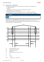
• Operating mode 1: SPG with qualified stop function (see chapter 4.4.1 "Operating mode 1 - Qualified
• Operating mode 4: Standard SPG with short tolerance times (see chapter 4.4.2 "Operating mode 4 -
standard with short tolerance times")
• Operating mode 5: Standard SPG (see chapter 4.4.3 "Operating mode 5 - Standard")
• Operating mode 6: SPG with qualified stop function and partial gating (see chapter 4.4.4 "Operating
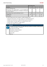
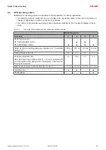
Tab. 4.1:
Overview of the functions in the individual operating modes
Operating mode
Functions
1
4
5
6
Performance Level
PL d with standard control
PL e with safety control
■
■
■
■
■
■
Minimum time for ending gating (see chapter 4.5.1 "Controlled
gating end")
100 ms
100 ms
100 ms
100 ms
Gating tolerance time t1
4 s
2 s
4 s
4 s


