Mounting
Leuze electronic GmbH + Co. KG
MLC 530 SPG
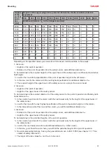
55
Height a
of the
point of
opera-
tion
[mm]
Height b of the upper edge of the protective field of the electro-sensitive protective
equipment
900
1000
1100
1200
1300
1400
1600
1800
2000
2200
2400
2600
Additional distance C
RO
to the danger zone [mm]
2000
950
950
850
850
800
750
700
550
400
0
0
0
1800
1100
1100
950
950
850
800
750
550
0
0
0
0
1600
1150
1150
1100
1000
900
850
750
450
0
0
0
0
1400
1200
1200
1100
1000
900
850
650
0
0
0
0
0
1200
1200
1200
1100
1000
850
800
0
0
0
0
0
0
1000
1200
1150
1050
950
750
700
0
0
0
0
0
0
800
1150
1050
950
800
500
450
0
0
0
0
0
0
600
1050
950
750
550
0
0
0
0
0
0
0
0
400
900
700
0
0
0
0
0
0
0
0
0
0
200
600
0
0
0
0
0
0
0
0
0
0
0
0
0
0
0
0
0
0
0
0
0
0
0
0
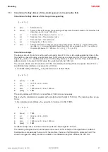
Depending on the specified values you can work with the above-mentioned table in three ways:
1. Given are:
• Height a of the point of operation
• Distance S of the point of operation from the safety sensor, and additional distance C
RO
To be determined is the required height b of the upper beam of the safety sensor and thereby its protective
field height.
Ä
Look for the line with the specification of the point of operation height in the left column.
Ä
In this line, look for the column with the next highest specification for additional distance C
RO
.
ð
The required height of the upper beam of the safety sensor is up top in the column head.
2. Given are:
• Height a of the point of operation
• Height b of the upper beam of the safety sensor
To be determined is the required distance S of the safety sensor to the point of operation and thereby addi-
tional distance C
RO
.
Ä
In the column head, look for the column with the next lowest entry for the height of the upper beam of
the safety sensor.
Ä
Look for the line with the next highest specification of the point of operation height a in this column.
ð
In the intersection point of the line and the column, you will find additional distance C
RO
.
3. Given are:
• Distance S of the point of operation from the safety sensor, and additional distance C
RO.
• Height b of the upper beam of the safety sensor
To be determined is the permitted height a of the point of operation.
Ä
In the column head, look for the column with the next lowest entry for the height of the upper beam of
the safety sensor.
Ä
Look for the next lowest value for real additional distance C
RO
in this column.
ð
In this line, go to the left column: here you will find the permitted height of the point of operation.
Ä
ð
The larger of the two values S
RT
and S
RO
is to be used.


