


Electrical connection
Leuze electronic
MSI-TRMB
31
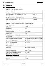
Figure 7.8: Safety monitoring device with two series connections consisting of multiple protective sen
-
sors with automatic start
Note the total delay time of the photoelectric sensors (0.5 ms to 8.5 ms)
+24V
Receiver
0V
Transmitter
MSI-TRMB
+24V
0V
active
State
Error
0V
+24V
Transmitter
0V
+24V
Receiver
0V
+24V
0V
Transmitter
+24V
0V
Receiver
active
active
Var. A
Var. B
S12
3
-A7
S21
-A1
S11
A1
S33
S34
S31 14
24
13
23
-K1
-K2
A1
A2
-K1
A1
A2
-K2
1
-A3
4
1
4
3
-A5
1
4
3
-A2
1
4
3
1
4
3
-A4
1
4
3
-A6
-K2
-K1
-K2
-K1
0V
+24V
0V
PE
+24V
PE
L-
L+
L+
L-
+24V
Receiver
Transmitter
+24V
0V
active
0V
+24V
Transmitter
0V
+24V
Receiver
0V
+24V
0V
Transmitter
+24V
0V
Receiver
active
active
3
-A8
1
-A11
4
1
4
3
-A13
1
4
3
-A9
1
4
3
1
4
3
-A12
1
4
3
-A14
S22
A2