v
Follow the suggested actions in the order in which they are listed in the Action column until the problem
is solved.
v
See the Chapter 8, “Parts Listing, TD200x Machine Types 3719, 3821, 3822, and 3823,” on page 237 to
determine which components are customer replaceable units (CRU) and which components are field
replaceable units (FRU).
v
If an action step is preceded by “(Trained service technician only),” that step must be performed only by a
trained service technician.
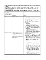
Lit EasyLED
diagnostics LED with
the system-error or
information LED also
lit
Description
Action
Memory (MEM)
A memory error has occurred.
Note:
The error LED on the DIMM
is also lit.
1. Determine whether the CNFG LED is also lit,
which indicates that the memory configuration is
invalid. Reinstall the DIMMs in a supported
configuration.
2. If the CNFG LED is not lit, one of the following
conditions might be present:
v
The server did not start and a failing DIMM LED
is lit:
a. Check for a PFA log event in the
system-event log.
b. Reseat the DIMM.
c. Move the DIMM to a different slot or replace
the DIMM.
d. (Trained service technician only) Replace
the system board.
v
The server started, the failing DIMM is disabled,
and the LED is lit:
a. If the LEDs are lit by two DIMMs, check the
system-event log for a PFA event on one of
the DIMMs, and then replace that DIMM.
Otherwise, replace both DIMMs.
b. If the LED is lit by only one DIMM, replace
that DIMM.
c. Re-enable the DIMM, using the Setup utility.
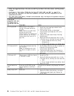
Microprocessor/
Memory Configuration
(CNFG)
A hardware configuration error has
occurred. (This LED is used with the
MEM, VRM, and CPU LEDs.)
1. (The system error LED, CPU LED, and this LED
are lit when POST detects a microprocessor
mismatch.) Remove and install two
microprocessors of the same cache size, type, and
clock speed.
2. (The system error LED, MEM LED, and this LED
are lit when POST detects an invalid memory
configuration.) Remove and install supported
DIMMs (see “Installing a memory module” on page
211).
3. (The system error LED, VRM LED, and this LED
are lit when POST detects a missing VRM.) Install
a VRM for microprocessor 2 (see “Installing a
voltage regulator module” on page 180).
4. Check the system error log for information
indicating incompatible components.
Chapter 5. Diagnostics
81
Содержание THINKSERVER 3719
Страница 1: ...ThinkServer TD200x Machine Types 3719 3821 3822 and 3823 Hardware Maintenance Manual ...
Страница 2: ......
Страница 3: ...ThinkServer TD200x Types 3719 3821 3822 and 3823 Hardware Maintenance Manual ...
Страница 12: ...4 ThinkServer TD200x Types 3719 3821 3822 and 3823 Hardware Maintenance Manual ...
Страница 22: ...14 ThinkServer TD200x Types 3719 3821 3822 and 3823 Hardware Maintenance Manual ...
Страница 28: ...20 ThinkServer TD200x Types 3719 3821 3822 and 3823 Hardware Maintenance Manual ...
Страница 34: ...26 ThinkServer TD200x Types 3719 3821 3822 and 3823 Hardware Maintenance Manual ...
Страница 244: ...236 ThinkServer TD200x Types 3719 3821 3822 and 3823 Hardware Maintenance Manual ...
Страница 258: ...250 ThinkServer TD200x Types 3719 3821 3822 and 3823 Hardware Maintenance Manual ...
Страница 282: ...274 ThinkServer TD200x Types 3719 3821 3822 and 3823 Hardware Maintenance Manual ...
Страница 286: ...278 ThinkServer TD200x Types 3719 3821 3822 and 3823 Hardware Maintenance Manual ...
Страница 296: ...288 ThinkServer TD200x Types 3719 3821 3822 and 3823 Hardware Maintenance Manual ...
Страница 303: ......
Страница 304: ...Part Number XXXXXX Printed in USA 1P P N XXXXXX ...


