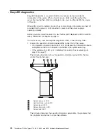
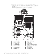
background image

v

Follow the suggested actions in the order in which they are listed in the Action column until the problem
is solved.

v

See the Chapter 8, “Parts Listing, TD200x Machine Types 3719, 3821, 3822, and 3823,” on page 237 to
determine which components are customer replaceable units (CRU) and which components are field
replaceable units (FRU).

v

If an action step is preceded by “(Trained service technician only),” that step must be performed only by a
trained service technician.

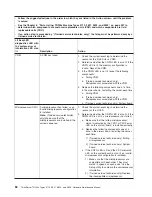
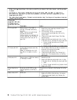
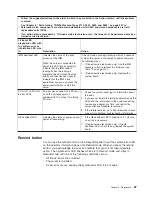
Lit EasyLED
diagnostics LED with
the system-error or
information LED also
lit

Description

Action

System board (BRD)

An error occurred on the system
board.

1. Check the LEDs on the system board to identify

the component that is causing the error. The BRD
LED can be lit for the following conditions:

v

Failed or missing battery

v

Failed voltage regulator

2. Check the system-event log for information about

the error.

3. Replace any failed or missing replaceable

components, such as the battery.

4. (Trained service technician only) If a voltage

regulator has failed, replace the system board.

PCI bus

A PCI adapter has failed.

1. See the system-event log (see “System-event log”

on page 38).

2. Check the LEDs on the PCI slots to identify the

component that is causing the error, and reseat the
failing adapter.

3. Replace the following components one at a time,

in the order shown, restarting the server each time:

a. Failing adapter

b. (Trained service technician only) System board

Fan

A fan has failed or is operating too
slowly.

1. Reinstall the removed fan.

2. If an individual fan LED is lit, replace the fan.

3. (Trained service technician only) Replace the

system board.

Power supply

A power supply has failed or has
been removed.

Note:

In a redundant power

configuration, the dc power LED on
one power supply might be off.

1. Check the individual power-supply LEDs.

2. Reseat the following components:

a. Power supply

b. (Trained service technician only) Power-supply

cage cables

3. Replace the following components one at a time,

in the order shown, restarting the server each time:

a. Power supply

b. (Trained service technician only) Power-supply

cage

Chapter 5. Diagnostics

79

Содержание THINKSERVER 3719

Страница 1: ...ThinkServer TD200x Machine Types 3719 3821 3822 and 3823 Hardware Maintenance Manual ...

Страница 2: ......

Страница 3: ...ThinkServer TD200x Types 3719 3821 3822 and 3823 Hardware Maintenance Manual ...

Страница 4: ...oration 2009 LENOVO products data computer software and services have been developed exclusively at private expense and are sold to governmental entities as commercial items as defined by 48 C F R 2 101 with limited and restricted rights to use reproduction and disclosure LIMITED AND RESTRICTED RIGHTS NOTICE If products data computer software or services are delivered pursuant a General Services A...

Страница 5: ...ems 25 Chapter 5 Diagnostics 27 Diagnostic tools 27 Event logs 27 Viewing event logs through the Setup utility 28 Viewing event logs without restarting the server 28 POST error codes 30 System event log 38 Integrated management module error messages 38 Troubleshooting tables 64 DVD drive problems 64 General problems 65 Hard disk drive problems 65 Intermittent problems 66 Keyboard mouse or pointing...

Страница 6: ...ing on the server 147 Turning off the server 148 Chapter 7 Installing optional devices and replacing customer replaceable units 149 Server components 149 Opening the bezel 150 Closing the bezel 151 Removing the bezel 152 Installing the bezel 154 Opening the bezel media door 155 Closing the bezel media door 156 Removing the left side cover 157 Installing the left side cover 158 Opening the power su...

Страница 7: ...odule 210 Installing a memory module 211 Independent channel mode 212 Memory mirroring mode 212 Removing a hot swap fan 217 Installing a hot swap fan 218 Removing a microprocessor and heat sink 218 Installing a microprocessor and heat sink 220 Thermal grease 226 Removing a heat sink retention module 227 Installing a heat sink retention module 228 Removing a microprocessor retention module 229 Inst...

Страница 8: ...ld Wide Web 275 Calling for service 275 Using other services 276 Purchasing additional services 277 Lenovo product service 277 Appendix B Notices 279 Trademarks 280 Important notes 280 Product recycling and disposal 281 Compliance with Republic of Turkey Directive on the Restriction of Hazardous Substances 282 Recycling statements for Japan 282 Battery return program 283 German Ordinance for Work ...

Страница 9: ...ailable at http www lenovo com support Before servicing a Lenovo product be sure to read the Safety Information See Chapter 2 Safety information on page 5 For information about the terms of the warranty and getting service and assistance see the Warranty and Support Information document Important Safety Information Be sure to read all caution and danger statements in this book before performing an...

Страница 10: ...xpects its suppliers to be ready to support Lenovo s requirements and schedule in the EU Products sold in 2005 will contain some RoHS compliant FRUs The following statement pertains to these products and any product Lenovo produces containing RoHS compliant parts RoHS compliant ThinkCentre parts have unique FRU part numbers Before or after June 2006 failed RoHS compliant parts must always be repla...

Страница 11: ...in Hazardous Substances in Electrical and Electronic Equipment EEE Türkiye EEE Yönetmeliğine Uygunluk Beyanı T C Çevre ve Orman Bakanlığı nın Elektrik ve Elektronik Eşyalarda Bazı Zararlı Maddelerin Kullanımının Sınırlandırılmasına Dair Yönetmelik EEE direktiflerine uygundur EEE Yönetmeliğ Bu Lenovo ürünü ine Uygundur Chapter 1 About this manual 3 ...

Страница 12: ...4 ThinkServer TD200x Types 3719 3821 3822 and 3823 Hardware Maintenance Manual ...

Страница 13: ...at tämän tuotteen lue turvaohjeet kohdasta Safety Information Avant d installer ce produit lisez les consignes de sécurité Vor der Installation dieses Produkts die Sicherheitshinweise lesen Prima di installare questo prodotto leggere le Informazioni sulla Sicurezza Les sikkerhetsinformasjonen Safety Information før du installerer dette produktet Antes de instalar este produto leia as Informações s...

Страница 14: ... Make sure that the exterior cover is not damaged loose or broken and observe any sharp edges 3 Check the power cord v Make sure that the third wire ground connector is in good condition Use a meter to measure third wire ground continuity for 0 1 ohm or less between the external ground pin and the frame ground v Make sure that the power cord is the correct type v Make sure that the insulation is n...

Страница 15: ...sition v Never assume that power has been disconnected from a circuit Check it to make sure that it has been disconnected v If you have to work on equipment that has exposed electrical circuits observe the following precautions Make sure that another person who is familiar with the power off controls is near you and is available to turn off the power if necessary When you are working with powered ...

Страница 16: ...statement is labeled Statement 1 translations for that caution statement are in the Safety Information document under Statement 1 Be sure to read all caution and danger statements in this document before you perform the procedures Read any additional safety information that comes with the server or optional device before you install the device Attention Use No 26 AWG or larger UL listed or CSA cer...

Страница 17: ...when there is evidence of fire water or structural damage v Disconnect the attached power cords telecommunications systems networks and modems before you open the device covers unless instructed otherwise in the installation and configuration procedures v Connect and disconnect cables as described in the following table when installing moving or opening covers on this product or attached devices T...

Страница 18: ...ith the same module type made by the same manufacturer The battery contains lithium and can explode if not properly used handled or disposed of Do not v Throw or immerse into water v Heat to more than 100 C 212 F v Repair or disassemble Dispose of the battery as required by local ordinances or regulations 10 ThinkServer TD200x Types 3719 3821 3822 and 3823 Hardware Maintenance Manual ...

Страница 19: ...v Use of controls or adjustments or performance of procedures other than those specified herein might result in hazardous radiation exposure DANGER Some laser products contain an embedded Class 3A or Class 3B laser diode Note the following Laser radiation when open Do not stare into the beam do not view directly with optical instruments and avoid direct exposure to the beam Class 1 Laser Product L...

Страница 20: ... and the power switch on the power supply do not turn off the electrical current supplied to the device The device also might have more than one power cord To remove all electrical current from the device ensure that all power cords are disconnected from the power source 1 2 12 ThinkServer TD200x Types 3719 3821 3822 and 3823 Hardware Maintenance Manual ...

Страница 21: ...blem with one of these parts contact a service technician Statement 26 CAUTION Do not place any object on top of rack mounted devices Attention This server is suitable for use on an IT power distribution system whose maximum phase to phase voltage is 240 V under any distribution fault condition Important This product is not suitable for use with visual display workplace devices according to Clause...

Страница 22: ...14 ThinkServer TD200x Types 3719 3821 3822 and 3823 Hardware Maintenance Manual ...

Страница 23: ...ovides a virtual presence capability for remote server management capabilities The IMM provides remote server management through industry standard interfaces Intelligent Platform Management Interface IPMI version 2 0 Simple Network Management Protocol SNMP version 3 Common Information Model CIM Web browser v Remote presence capability and blue screen capture The remote presence feature provides th...

Страница 24: ...thernet controller which supports connection to a 10 Mbps 100 Mbps or 1000 Mbps network For more information see Enabling the Broadcom Gigabit Ethernet Utility program on page 266 v Intelligent Platform Management Interface IPMI 2 0 IPMI 2 0 support providing secure remote power on power off and several standard alerts for components such as fans voltage and temperature v Large data storage capaci...

Страница 25: ...ions v Symmetric multiprocessing SMP The server supports up to two Intel Xeon quad core microprocessors If the server comes with only one microprocessor you can install an additional microprocessor to enhance performance and provide SMP capability v Systems management capabilities The server contains an Integrated Management Module IMM which enables you to manage the functions of the server locall...

Страница 26: ...l ATA SATA controller v Serial over LAN SOL and serial redirection over Telnet or Secure Shell SSH v Support for remote management presence v One systems management RJ 45 for connection to a dedicated systems management network v EasyLED diagnostics v Six Universal Serial Bus USB ports standard v2 0 supporting v1 1 Four on rear of server Two on front of server v One internal USB tape connector v O...

Страница 27: ...tion see Using the ThinkServer EasyStartup DVD on page 263 EasyManage The ThinkServer EasyManage Core Server provides centralized hardware and software inventory management and secure automated system management through a centralized console The ThinkServer EasyManage Agent enables other clients on the network to be managed by the centralized console The ThinkServer EasyManage Core Server is suppo...

Страница 28: ...20 ThinkServer TD200x Types 3719 3821 3822 and 3823 Hardware Maintenance Manual ...

Страница 29: ... this happens correct the cause of the first error message The other error messages usually will not occur the next time you run the diagnostic programs Exception If multiple error codes or EasyLED diagnostics LEDs indicate a microprocessor error the error might be in a microprocessor or in a microprocessor socket See Microprocessor problems on page 69 for information about diagnosing microprocess...

Страница 30: ...ositions e Turn on all external devices f Turn on the server If the server does not start see Troubleshooting tables on page 64 g Check the system error LED on the operator information panel see Chapter 6 Locating Server Controls and connectors on page 127 If it is flashing check the EasyLED diagnostics LEDs see EasyLED diagnostics on page 76 h Check for the following results v Successful completi...

Страница 31: ...rmware software and operating system Have this information available when you contact Lenovo or an approved warranty service provider For instructions for running the DSA program see Running the diagnostic programs on page 90 If you have to download the latest version of DSA complete the following steps Note Changes are made periodically to the Lenovo Web site The actual procedure might vary sligh...

Страница 32: ... that has been enabled can stop working 1 Make sure that all installed hardware and software are supported See http www lenovo com thinkserver to verify that the server supports the installed operating system optional devices and software levels If any hardware or software component is not supported uninstall it to determine whether it is causing the problem You must remove nonsupported hardware b...

Страница 33: ...nostic v Hints and tips are under Troubleshoot d Check for and replace defective hardware If a hardware component is not operating within specifications it can cause unpredictable results Most hardware failures are reported as error codes in a system or operating system log For more information see Troubleshooting tables on page 64 and Chapter 7 Installing optional devices and replacing customer r...

Страница 34: ...26 ThinkServer TD200x Types 3719 3821 3822 and 3823 Hardware Maintenance Manual ...

Страница 35: ...e diagnostic programs are the primary method of testing the major components of the server See Diagnostic programs messages and error codes on page 90 for more information Event logs Error codes and messages are displayed in the following types of event logs v POST event log This log contains the three most recent error codes and messages that were generated during POST You can view the POST event...

Страница 36: ... select POST Event Viewer v To view the system event log select System Event Log Viewing event logs without restarting the server If the server is not hung methods are available for you to view one or more event logs without having to restart the server You can use the DSA Preboot to view the system event log as the IPMI event log the IMM event log as the ASM event log or the merged DSA log You mu...

Страница 37: ...r is not hung and is not connected to a network Use IPMItool locally to view the system event log The server is hung v If DSA Preboot is installed restart the server and press F2 to start DSA Preboot and view the event logs v If DSA Preboot is not installed insert the DSA Preboot CD and restart the server to start DSA Preboot and view the event logs v Alternatively you can restart the server and p...

Страница 38: ...ained service technician only that step must be performed only by a trained service technician Error code Description Action 0010002 Microprocessor not supported 1 Reseat the following components one at a time in the order shown restarting the server each time a Trained service technician only Microprocessor 1 b Trained service technician only Microprocessor 2 if one is installed 2 Trained service...

Страница 39: ... one at a time in the order shown restarting the server each time a Trained service technician only Microprocessor b Trained service technician only System board 001100A Microcode update failed 1 Update the server firmware see Updating the firmware on page 267 2 Trained service technician only Replace the microprocessor 0050001 DIMM disabled 1 If the server fails the POST memory test reseat the DI...

Страница 40: ...ailing DIMM which is indicated by a lit LED on the system board 0058007 DIMM population is unsupported 1 Reseat the DIMMs and then restart the server 2 Remove the lowest numbered DIMM pair of those that are identified replace it with an identical pair of known good DIMMs and then restart the server Repeat as necessary If the failures continue go to step 4 3 Return the removed DIMMs one pair at a t...

Страница 41: ...t the battery 2 Clear the CMOS memory see System board switches and jumpers on page 144 3 Replace the following components one at a time in the order shown restarting the server each time a Battery b Trained service technician only System board 2011000 PCI X PERR 1 Check the extender card LEDs 2 Reseat all affected adapters and extender cards 3 Update the PCI device firmware 4 Remove the adapters ...

Страница 42: ...ers in the PCI slots to change the load order of the optional device ROM code 2 Run the Setup utility select Start Options and change the boot priority to change the load order of the optional device ROM code 3 Run the Setup utility and disable some other resources if their functions are not being used to make more space available Select Devices and I O Ports to disable any of the integrated devic...

Страница 43: ...rce and then turn on the server 305000A RTC date time is incorrect 1 Adjust the date and time settings in the Setup utility and then restart the server 2 Reseat the battery 3 Replace the following components one at a time in the order shown restarting the server each time a Battery b Trained service technician only System board 3058001 System configuration invalid 1 Run the Setup utility and selec...

Страница 44: ...battery clear event 3138002 Boot configuration error 1 Remove any recent configuration changes that you made in the Setup utility 2 Run the Setup utility select Load Default Settings and save the settings 3808000 IMM communication failure 1 Remove power from the server for 30 seconds and then reconnect the server to power and restart it 2 Update the IMM firmware 3 Trained service technician only R...

Страница 45: ...3 Core Root of Trust Measurement CRTM flash lock failed 1 Run the Setup utility select Load Default Settings and save the settings 2 Trained service technician only Replace the system board 3818004 Core Root of Trust Measurement CRTM system error 1 Run the Setup utility select Load Default Settings and save the settings 2 Trained service technician only Replace the system board 3818005 Current Ban...

Страница 46: ...sensor Ambient Temp going high upper critical has asserted Error An upper critical sensor going high has asserted Reduce the ambient temperature Numeric sensor Ambient Temp going high upper non recoverable has asserted Error An upper nonrecoverable sensor going high has asserted Reduce the ambient temperature Numeric sensor Planar 3 3V going low lower critical has asserted Error A lower critical s...

Страница 47: ... condition has occurred 1 Make sure that the latest levels of firmware and device drivers are installed for all adapters and standard devices such as Ethernet SCSI and SAS Important Some cluster solutions require specific code levels or coordinated code updates If the device is part of a cluster solution verify that the latest level of code is supported for the cluster solution before you update t...

Страница 48: ...vice is part of a cluster solution verify that the latest level of code is supported for the cluster solution before you update the code 2 Make sure that the installed microprocessors are compatible with each other see Installing a microprocessor and heat sink on page 220 for information about microprocessor requirements 3 Trained service technician only Reseat microprocessor n 4 Trained service t...

Страница 49: ...ution verify that the latest level of code is supported for the cluster solution before you update the code 2 Make sure that the installed microprocessors are compatible with each other see Installing a microprocessor and heat sink on page 220 for information about microprocessor requirements 3 Trained service technician only Reseat microprocessor n 4 Trained service technician only Replace microp...

Страница 50: ...place microprocessor n n microprocessor number Sensor CPU nOverTemp has transitioned to critical from a non recoverable state n microprocessor number Error A sensor has changed to Critical state from Nonrecoverable state 1 Make sure that the fans are operating that there are no obstructions to the airflow that the air baffle is in place and correctly installed and that the server cover is installe...

Страница 51: ...on panel A bus timeout has occurred on system 1 1 CIM_ComputerSystem ElementName Error A bus timeout has occurred 1 Remove the adapter from the PCI slot that is indicated by a lit LED 2 Replace the extender card 3 Remove all PCI adapters 4 Trained service technicians only Replace the system board A software NMI has occurred on system 1 1 CIM_ComputerSystem ElementName Error A software NMI has occu...

Страница 52: ...ordinated code updates If the device is part of a cluster solution verify that the latest level of code is supported for the cluster solution before you update the code 2 Trained service technician only Replace the system board A Uncorrectable Bus Error has occurred on system 1 1 CIM_ComputerSystem ElementName Error A bus uncorrectable error has occurred Sensor Critical Int PCI 1 Check the system ...

Страница 53: ...equire specific code levels or coordinated code updates If the device is part of a cluster solution verify that the latest level of code is supported for the cluster solution before you update the code 5 Make sure that the two microprocessors are matching 6 Trained service technician only Replace the system board A Uncorrectable Bus Error has occurred on system 1 1 CIM_ComputerSystem ElementName E...

Страница 54: ... device is part of a cluster solution verify that the latest level of code is supported for the cluster solution before you update the code 5 Trained service technician only Replace the system board The Power Supply Power Supply n has Failed n power supply number Error Power supply nhas failed n power supply number 1 If the power on LED is lit complete the following steps a Reduce the server to th...

Страница 55: ... Trained service technician only Remove the PCI adapter and microprocessor 1 Reinstall the microprocessor in socket 1 and restart the server 3 Restart the server 4 Reinstall each device one at a time starting the server each time to isolate the failing device 5 Replace the failing device 6 Trained service technician only Replace the system board Sensor Pwr Rail B Fault has transitioned to non reco...

Страница 56: ...ailing device 6 Trained service technician only Replace the system board Sensor Pwr Rail D Fault has transitioned to non recoverable Error A sensor has changed to Nonrecoverable state 1 Turn off the server and disconnect it from power 2 Remove the optical drive and the DIMMs in connectors 9 through 16 3 Restart the server 4 Reinstall the microprocessor in socket 1 and restart the server 5 Trained ...

Страница 57: ...only Replace the system board Sensor PS n Therm Fault has transitioned to critical from a less severe state n power supply number Error A sensor has changed to Critical state from a less severe state 1 Make sure that there are no obstructions such as bundled cables to the airflow from the power supply fan 2 Replace power supply n n power supply number Sensor PSn 12V OV Fault has transitioned to no...

Страница 58: ...e 1 Check the power supply LED on the EasyLED panel see EasyLED diagnostics on page 76 2 Replace the failing power supply n power supply number Redundancy Power Unit has been reduced Error Redundancy has been lost and is insufficient to continue operation 1 Check the LEDs for both power supplies 2 Follow the actions in Power supply LEDs on page 88 Redundancy Cooling Zone 1 has been reduced Error R...

Страница 59: ...ard disk drive for which the status LED is lit 3 Replace the defective hard disk drive The Drive n Status has been removed from unit Drive 0 Status n hard disk drive number Error A drive has been removed Reseat hard disk drive n n hard disk drive number The Drive n Status has been disabled due to a detected fault n hard disk drive number Error A drive has been disabled because of a fault 1 Run the...

Страница 60: ...mory logging limit has been reached 1 Update the server firmware to the latest level Important Some cluster solutions require specific code levels or coordinated code updates If the device is part of a cluster solution verify that the latest level of code is supported for the cluster solution before you update the code 2 Reseat the DIMMs and run the DSA memory test 3 Replace any DIMM that is indic...

Страница 61: ...or for One of the DIMMs on Memory Subsystem One of the DIMMs Error A DIMM configuration error has occurred Make sure that DIMMs are installed in the correct sequence and have the same size type speed and technology Memory uncorrectable error detected for DIMM n Status on Memory Subsystem DIMM n Status n DIMM number Error A memory uncorrectable error has occurred 1 If the server failed the POST mem...

Страница 62: ...Critical state from a less severe state 1 Make sure that the fans are operating that there are no obstructions to the airflow that the air baffles are in place and correctly installed and that the server cover is installed and completely closed 2 If a fan has failed complete the action for a fan failure 3 Replace DIMM n n DIMM number A PCI PERR has occurred on system 1 1 CIM_ComputerSystem Element...

Страница 63: ... require specific code levels or coordinated code updates If the device is part of a cluster solution verify that the latest level of code is supported for the cluster solution before you update the code 4 Remove the adapter from slot n 5 Replace the PCIe adapter 6 Replace extender card n n PCI slot number A PCI PERR has occurred on system 1 1 CIM_ComputerSystem ElementName Error A PCI PERR has oc...

Страница 64: ...r coordinated code updates If the device is part of a cluster solution verify that the latest level of code is supported for the cluster solution before you update the code 4 Remove both adapters 5 Replace the PCIe adapter 6 Replace the extender card 7 Trained service technician only Replace the system board Fault in slot System board on system 1 1 CIM_ComputerSystem ElementName Error 1 Check the ...

Страница 65: ...tificate must contain a public key that corresponds to the key pair that was previously generated by the Generate a New Key and Certificate Signing Request link 1 Make sure that the certificate that you are importing is correct 2 Try importing the certificate again Ethernet Data Rate modified from 1 to 2 by user 3 1 CIM_EthernetPort Speed 2 CIM_EthernetPort Speed 3 user ID Info A user has modified...

Страница 66: ...SubnetMask 2 CIM_StaticIPAssignment SettingData SubnetMask 3 user ID Info A user has modified the IP subnet mask of the IMM No action information only IP address of default gateway modified from 1 to 2 by user 3s 1 CIM_IPProtocolEndpoint GatewayIPv4Address 2 CIM_StaticIPAssignment SettingData DefaultGatewayAddress 3 user ID Info A user has modified the default gateway IP address of the IMM No acti...

Страница 67: ...ilures currently set to 5 in the firmware 3 IP address xxx xxx xxx xxx Error A user has exceeded the maximum number of unsuccessful login attempts from the command line interface and has been prevented from logging in for the lockout period 1 Make sure that the correct login ID and password are being used 2 Have the system administrator reset the login ID or password Remote access attempt failed I...

Страница 68: ...GatewayAddress Info An IMM IP address and configuration have been assigned using client data No action information only LAN Ethernet 0 interface is no longer active Info The IMM Ethernet interface has been disabled No action information only LAN Ethernet 0 interface is now active Info The IMM Ethernet interface has been enabled No action information only DHCP setting changed to by user 1 1 user ID...

Страница 69: ...r solution before you update the code Running the backup IMM main application Error The IMM has resorted to running the backup main application Update the IMM firmware Important Some cluster solutions require specific code levels or coordinated code updates If the device is part of a cluster solution verify that the latest level of code is supported for the cluster solution before you update the c...

Страница 70: ...ssor No action information only Flash of 1 from 2 failed for user 3 1 CIM_ManagedElement ElementName 2 Web or LegacyCLI 3 user ID Info An attempt to update a firmware component from the interface and IP address has failed Try to update the firmware again The Chassis Event Log CEL on system 1 is 75 full 1 CIM_ComputerSystem ElementName Info The IMM event log is 75 full When the log is full older lo...

Страница 71: ...ervice technician only that step must be performed only by a trained service technician Security Userid 1 had 2 login failures from an SSH client at IP address 3 1 user ID 2 MaximumSuccessiveLoginFailures currently set to 5 in the firmware 3 IP address xxx xxx xxx xxx Error A user has exceeded the maximum number of unsuccessful login attempts from SSH and has been prevented from logging in for the...

Страница 72: ...7 to determine which components are customer replaceable units CRU and which components are field replaceable units FRU v If an action step is preceded by Trained service technician only that step must be performed only by a trained service technician Symptom Action The DVD drive is not recognized 1 Make sure that v The SATA channel to which the DVD drive is attached primary or secondary is enable...

Страница 73: ...ing or a similar problem has occurred If the part is a CRU replace it If the part is a FRU the part must be replaced by a trained service technician Hard disk drive problems v Follow the suggested actions in the order in which they are listed in the Action column until the problem is solved v See Chapter 8 Parts Listing TD200x Machine Types 3719 3821 3822 and 3823 on page 237 to determine which co...

Страница 74: ...gested actions in the order in which they are listed in the Action column until the problem is solved v See Chapter 8 Parts Listing TD200x Machine Types 3719 3821 3822 and 3823 on page 237 to determine which components are customer replaceable units CRU and which components are field replaceable units FRU v If an action step is preceded by Trained service technician only that step must be performe...

Страница 75: ... during startup 4 If you are using a USB keyboard and it is connected to a USB hub disconnect the keyboard from the hub and connect it directly to the server 5 Replace the following components one at a time in the order shown restarting the server each time a Keyboard b Trained service technician only System board The mouse or pointing device does not work 1 Make sure that v The mouse or pointing ...

Страница 76: ...upt SMI replace the DIMM v If a DIMM was disabled by the user or by POST run the Setup utility and enable the DIMM 3 Run memory diagnostics see Running the diagnostic programs on page 90 4 Make sure that there is no memory mismatch when the server is at the minimum memory configuration two 512 MB DIMMs see the information about the minimum required configuration on page Solving undetermined proble...

Страница 77: ...and that the microprocessors match in speed and cache size 3 Trained service technician only Reseat microprocessor 1 4 Trained service technician only If there is no indication of which microprocessor has failed isolate the error by testing with one microprocessor at a time 5 Replace the following components one at a time in the order shown restarting the server each time a Trained service technic...

Страница 78: ...erver is attached to a KVM switch bypass the KVM switch to eliminate it as a possible cause of the problem connect the monitor cable directly to the correct connector on the rear of the server 2 Make sure that v The server is turned on If there is no power to the server see Power problems on page 73 v The monitor cables are connected correctly v The monitor is turned on and the brightness and cont...

Страница 79: ...dable rolling or distorted screen images If this happens turn off the monitor Attention Moving a color monitor while it is turned on might cause screen discoloration Move the device and the monitor at least 305 mm 12 in apart and turn on the monitor Notes a To prevent diskette drive read write errors make sure that the distance between the monitor and any external diskette drive is at least 76 mm ...

Страница 80: ...led correctly v You have not loosened any other installed devices or cables v You updated the configuration information in the Setup utility Whenever memory or any other device is changed you must update the configuration 2 Reseat the device that you just installed 3 Replace the device that you just installed An optional device that used to work does not work now 1 Make sure that all of the hardwa...

Страница 81: ...v The LEDs on the power supply do not indicate a problem v The microprocessors are installed in the correct sequence 3 Reseat the following components a DIMMs b Trained service technician only Power switch connector c Trained service technician only Power backplane 4 Replace the following components one at a time in the order shown restarting the server each time a DIMMs b Trained service technici...

Страница 82: ...hich components are field replaceable units FRU v If an action step is preceded by Trained service technician only that step must be performed only by a trained service technician Symptom Action The number of serial ports that are identified by the operating system is less than the number of installed serial ports 1 Make sure that v Each port is assigned a unique address in the Setup utility and n...

Страница 83: ...comes with the software for a description of the messages and suggested solutions to the problem 3 Contact the software vendor Universal Serial Bus USB port problems v Follow the suggested actions in the order in which they are listed in the Action column until the problem is solved v See Chapter 8 Parts Listing TD200x Machine Types 3719 3821 3822 and 3823 on page 237 to determine which components...

Страница 84: ...LED diagnostics LEDs in the following order 1 Look at the operator information panel LEDs on the front of the server v If an operator information panel LED is lit it indicates that information about a suboptimal condition in the server is available in the system event log v If the system error LED is lit it indicates that an error has occurred go to step 2 on page 77 The following illustration sho...

Страница 85: ...ive v Flashing slowly once per second The server is turned off and is ready to be turned on You can press the power control button to turn on the server v Lit The server is turned on v Fading on and off The server is in a reduced power state To wake the server press the power control button or use the IMM Web interface Hard disk drive activity green When this LED is flashing rapidly it indicates t...

Страница 86: ...its CRU and which components are field replaceable units FRU v If an action step is preceded by Trained service technician only that step must be performed only by a trained service technician Lit EasyLED diagnostics LED with the system error or information LED also lit Description Action System event log LOG A system error occurred View the contents of the system event log see Event logs on page ...

Страница 87: ...y 4 Trained service technician only If a voltage regulator has failed replace the system board PCI bus A PCI adapter has failed 1 See the system event log see System event log on page 38 2 Check the LEDs on the PCI slots to identify the component that is causing the error and reseat the failing adapter 3 Replace the following components one at a time in the order shown restarting the server each t...

Страница 88: ...curred Notes 1 This LED is also lit when a hard disk drive is removed from the server 2 The error LED on the failing hard disk drive is also lit 3 Check the system event log for a RAID error 1 Reinstall the removed drive 2 Reseat the following components a Failing hard disk drive b SAS hard disk drive backplane c SAS signal and power cables d System board e ServeRAID adapter 3 Replace the componen...

Страница 89: ...e the DIMM to a different slot or replace the DIMM d Trained service technician only Replace the system board v The server started the failing DIMM is disabled and the LED is lit a If the LEDs are lit by two DIMMs check the system event log for a PFA event on one of the DIMMs and then replace that DIMM Otherwise replace both DIMMs b If the LED is lit by only one DIMM replace that DIMM c Re enable ...

Страница 90: ...y Microprocessor associated with the VRM c Trained service technician only System board Microprocessor CPU A microprocessor has failed or an invalid microprocessor configuration is installed Note Trained service technician only Make sure that the microprocessors are installed in the correct sequence 1 Check the system event log to determine the reason for the lit LED 2 Determine whether the CNFG L...

Страница 91: ...t step must be performed only by a trained service technician Lit EasyLED diagnostics LED with the system error or information LED also lit Description Action Service processor bus SP BUS The IMM detects an internal error 1 Disconnect the server from ac power then reconnect the server to power and restart the server 2 Update the IMM firmware Look at the system service label on the top of the serve...

Страница 92: ... Battery error LED 2 PCI slot 2 error LED 10 System board error LED 3 PCI slot 3 error LED 11 VRM fail LED 4 HS heartbeat LED 12 CPU 1 error LED 5 PCI slot 4 error LED 13 DIMMs 1 8 error LEDs starting from the bottom 6 PCI slot 5 error LED 14 DIMMs 9 16 error LEDs starting from the bottom 7 PCI slot 6 error LED 15 CPU 2 error LED 8 IMM heartbeat LED 16 CPU mismatch LED 84 ThinkServer TD200x Types ...

Страница 93: ...ly by a trained service technician Lit EasyLED diagnostics LED with the system error or information LED also lit Description Action DIMM 1 to DIMM 16 error LEDs A DIMM has failed or is incorrectly installed 1 Remove the DIMM that is indicated by a lit error LED 2 Reseat the DIMM 3 Replace the following components one at a time in the order shown restarting the server each time a DIMM b Trained ser...

Страница 94: ... the failing microprocessor 4 Replace the following components one at a time in the order shown restarting the server each time a Trained service technician only Failing microprocessor b Trained service technician only System board CPU mismatch LED A mismatched microprocessor has been installed Note All microprocessors must have the same speed and cache size 1 Run the Setup utility and view the mi...

Страница 95: ...page 144 2 Trained service technician only Replace the system board PCI slot 1 to PCI slot 8 error LEDs An error has occurred on a PCI bus or on the system board An additional LED is lit next to a failing PCI slot 1 Check the system event log for information about the error 2 If you cannot isolate the failing adapter through the LEDs and the information in the system event log remove one adapter a...

Страница 96: ...LED 3 Power error LED The following table describes the problems that are indicated by various combinations of the power supply LEDs and the system power LED on the operator information panel and suggested actions to correct the detected problems 88 ThinkServer TD200x Types 3719 3821 3822 and 3823 Hardware Maintenance Manual ...

Страница 97: ...ake sure that the power cord is connected to a functioning power source This happens only when a second power supply is providing power to the server Off On Off Faulty power supply Replace the power supply Off On On Faulty power supply Replace the power supply On Off Off Power supply not fully seated faulty system board or faulty power supply 1 Reseat the power supply 2 If the system board error L...

Страница 98: ... to display the graphical user interface or select cmd to display the DSA interactive menu 6 Follow the instructions on the screen to select the diagnostic test to run If the diagnostic programs do not detect any hardware errors but the problem remains during normal server operations a software error might be the cause If you suspect a software problem see the information that comes with your soft...

Страница 99: ...nd specify a location and name for the saved log file Notes 1 To create and use a diskette you must add an optional external diskette drive to the server 2 To save the test log to a diskette you must use a diskette that you have formatted yourself this function does not work with preformatted diskettes If the diskette has sufficient space for the test log the diskette can contain other data Diagno...

Страница 100: ... at a time in the order shown and run this test again to determine whether the problem has been solved a Trained service technician only Microprocessor board b Trained service technician only Microprocessor 9 If the failure remains go to the Lenovo Web site for more troubleshooting information at http www lenovo com support 089 802 xxx CPU CPU Stress Test Aborted System resource availability error...

Страница 101: ...t the system if necessary to recover from a hung state 7 Run the test again 8 Replace the following components one at a time in the order shown and run this test again to determine whether the problem has been solved a Trained service technician only Microprocessor board b Trained service technician only Microprocessor 9 If the failure remains go to the Lenovo Web site for more troubleshooting inf...

Страница 102: ...that the IMM firmware is at the latest level The installed firmware level is shown in the DSA log in the Firmware VPD section for this component For more information see Updating the firmware on page 267 6 Run the test again 7 If the failure remains go to the Lenovo Web site for more troubleshooting information at http www lenovo com support 166 803 xxx IMM IMM I2C Test Aborted IMM I2C test stoppe...

Страница 103: ... sure that the IMM firmware is at the latest level The installed firmware level is shown in the DSA log in the Firmware VPD section for this component For more information see Updating the firmware on page 267 6 Run the test again 7 If the failure remains go to the Lenovo Web site for more troubleshooting information at http www lenovo com support 166 805 xxx IMM IMM I2C Test Aborted IMM I2C test ...

Страница 104: ...that the IMM firmware is at the latest level The installed firmware level is shown in the DSA log in the Firmware VPD section for this component For more information see Updating the firmware on page 267 6 Run the test again 7 If the failure remains go to the Lenovo Web site for more troubleshooting information at http www lenovo com support 166 807 xxx IMM IMM I2C Test Aborted IMM I2C test stoppe...

Страница 105: ...latest level 5 Make sure that the IMM firmware is at the latest level The installed firmware level is shown in the DSA log in the Firmware VPD section for this component For more information see Updating the firmware on page 267 6 Run the test again 7 If the failure remains go to the Lenovo Web site for more troubleshooting information at http www lenovo com support 166 809 xxx IMM IMM I2C Test Ab...

Страница 106: ...re is at the latest level The installed firmware level is shown in the DSA log in the Firmware VPD section for this component For more information see Updating the firmware on page 267 6 Run the test again 7 If the failure remains go to the Lenovo Web site for more troubleshooting information at http www lenovo com support 166 811 xxx IMM IMM I2C Test Aborted IMM I2C test stopped request data fiel...

Страница 107: ...sure that the IMM firmware is at the latest level The installed firmware level is shown in the DSA log in the Firmware VPD section for this component For more information see Updating the firmware on page 267 6 Run the test again 7 If the failure remains go to the Lenovo Web site for more troubleshooting information at http www lenovo com support 166 813 xxx IMM IMM I2C Test Aborted IMM I2C test s...

Страница 108: ...he IMM firmware is at the latest level The installed firmware level is shown in the DSA log in the Firmware VPD section for this component For more information see Updating the firmware on page 267 6 Run the test again 7 If the failure remains go to the Lenovo Web site for more troubleshooting information at http www lenovo com support 166 815 xxx IMM IMM I2C Test Aborted IMM I2C test stopped inva...

Страница 109: ... latest level 5 Make sure that the IMM firmware is at the latest level The installed firmware level is shown in the DSA log in the Firmware VPD section for this component For more information see Updating the firmware on page 267 6 Run the test again 7 If the failure remains go to the Lenovo Web site for more troubleshooting information at http www lenovo com support 166 817 xxx IMM IMM I2C Test A...

Страница 110: ...test level The installed firmware level is shown in the DSA log in the Firmware VPD section for this component For more information see Updating the firmware on page 267 6 Run the test again 7 If the failure remains go to the Lenovo Web site for more troubleshooting information at http www lenovo com support 166 819 xxx IMM IMM I2C Test Aborted IMM I2C test stopped a command response could not be ...

Страница 111: ... latest level 5 Make sure that the IMM firmware is at the latest level The installed firmware level is shown in the DSA log in the Firmware VPD section for this component For more information see Updating the firmware on page 267 6 Run the test again 7 If the failure remains go to the Lenovo Web site for more troubleshooting information at http www lenovo com support 166 821 xxx IMM IMM I2C Test A...

Страница 112: ...at the latest level The installed firmware level is shown in the DSA log in the Firmware VPD section for this component For more information see Updating the firmware on page 267 6 Run the test again 7 If the failure remains go to the Lenovo Web site for more troubleshooting information at http www lenovo com support 166 823 xxx IMM IMM I2C Test Aborted IMM I2C test stopped cannot execute the comm...

Страница 113: ...evel is shown in the DSA log in the Firmware VPD section for this component For more information see Updating the firmware on page 267 6 Run the test again 7 If the failure remains go to the Lenovo Web site for more troubleshooting information at http www lenovo com support 166 901 xxx IMM IMM I2C Test Failed The IMM indicates a failure in the H8 bus Bus 0 1 Turn off the system and disconnect it f...

Страница 114: ...conds reconnect the system to the power source and turn on the system 3 Run the test again 4 Make sure that the DSA code is at the latest level 5 Make sure that the IMM firmware is at the latest level The installed firmware level is shown in the DSA log in the Firmware VPD section for this component For more information see Updating the firmware on page 267 6 Run the test again 7 Turn off the syst...

Страница 115: ... again 4 Make sure that the DSA code is at the latest level 5 Make sure that the IMM firmware is at the latest level The installed firmware level is shown in the DSA log in the Firmware VPD section for this component For more information see Updating the firmware on page 267 6 Run the test again 7 Disconnect the system from the power source 8 Replace the DIMMs one at a time and run the test again ...

Страница 116: ... disconnect the system from ac power to reset the IMM 2 After 45 seconds reconnect the system to the power source and turn on the system 3 Run the test again 4 Make sure that the DSA code is at the latest level 5 Make sure that the IMM firmware is at the latest level The installed firmware level is shown in the DSA log in the Firmware VPD section for this component For more information see Updatin...

Страница 117: ... disconnect the system from ac power to reset the IMM 2 After 45 seconds reconnect the system to the power source and turn on the system 3 Run the test again 4 Make sure that the DSA code is at the latest level 5 Make sure that the IMM firmware is at the latest level The installed firmware level is shown in the DSA log in the Firmware VPD section for this component For more information see Updatin...

Страница 118: ...eplace the system board 9 Reconnect the system to the power source and turn on the system 10 Run the test again 11 If the failure remains go to the Lenovo Web site for more troubleshooting information at http www lenovo com support 201 801 xxx Memory Memory Test Aborted Test aborted the server firmware programmed the memory controller with an invalid CBAR address 1 Turn off and restart the system ...

Страница 119: ...er firmware is at the latest level The installed firmware level is shown in the DSA log in the Firmware VPD section for this component For more information see Updating the firmware on page 267 4 Run the test again 5 If the failure remains go to the Lenovo Web site for more troubleshooting information at http www lenovo com support 201 805 xxx Memory Memory Test Aborted Test aborted the memory con...

Страница 120: ...are level is shown in the DSA log in the Firmware VPD section for this component For more information see Updating the firmware on page 267 4 Run the test again 5 If the failure remains go to the Lenovo Web site for more troubleshooting information at http www lenovo com support 201 809 xxx Memory Memory Test Aborted Test aborted program error operation running fast scrub 1 Turn off and restart th...

Страница 121: ...ware level is shown in the DSA log in the Firmware VPD section for this component For more information see Updating the firmware on page 267 6 Run the test again 7 Replace the failing DIMMs 8 Re enable all memory in the Setup utility see Using the Setup Utility on page 252 9 Run the test again 10 Replace the failing DIMM 11 If the failure remains go to the Lenovo Web site for more troubleshooting ...

Страница 122: ...upport 202 901 xxx Memory Memory Stress Test Failed Test failure 1 Run the standard memory test to validate all memory 2 Make sure that the DSA code is at the latest level 3 Turn off the system and disconnect it from power 4 Reseat the DIMMs 5 Reconnect the system to power and turn on the system 6 Run the test again 7 If the failure remains go to the Lenovo Web site for more troubleshooting inform...

Страница 123: ...ke sure that the DSA code is at the latest level 8 Run the test again 9 Replace the CD DVD drive 10 If the failure remains go to the Lenovo Web site for more troubleshooting information at http www lenovo com support 215 803 xxx Optical Drive v Verify Media Installed v Read Write Test v Self Test Messages and actions apply to all three tests Failed The disc might be in use by the system 1 Wait for...

Страница 124: ...ive v Verify Media Installed v Read Write Test v Self Test Messages and actions apply to all three tests Aborted Could not access the drive 1 Insert a CD DVD into the drive or try a new media and wait for 15 seconds 2 Run the test again 3 Check the drive cabling at both ends for loose or broken connections or damage to the cable Replace the cable if it is damaged 4 Run the test again 5 Make sure t...

Страница 125: ...the error log 4 Run the test again 5 If the failure remains go to the Lenovo Web site for more troubleshooting information at http www lenovo com support 264 902 000 Tape Drive Tape Drive Test Failed Media is not detected 1 Clean the tape drive using the appropriate cleaning media and install new media 2 Run the test again 3 Clear the error log 4 Run the test again 5 If the failure remains go to t...

Страница 126: ... remains go to the Lenovo Web site for more troubleshooting information at http www lenovo com support 405 901 xxx Broadcom Ethernet Device Test Control Registers Failed 1 Make sure that the component firmware is at the latest level The installed firmware level is shown in the DSA log in the Firmware VPD section for this component For more information see Updating the firmware on page 267 2 Run th...

Страница 127: ...rmation and Network Settings information in the DSA log to determine the physical location of the failing component 4 If the failure remains go to the Lenovo Web site for more troubleshooting information at http www lenovo com support 405 903 xxx Broadcom Ethernet Device Test Internal Memory Failed 1 Make sure that the component firmware is at the latest level The installed firmware level is shown...

Страница 128: ...bleshooting information at http www lenovo com support 405 905 xxx Broadcom Ethernet Device Test Loop back at MAC Layer Failed 1 Make sure that the component firmware is at the latest level The installed firmware level is shown in the DSA log in the Firmware VPD section for this component For more information see Updating the firmware on page 267 2 Run the test again 3 Replace the component that i...

Страница 129: ...Test State Description Action 405 907 xxx Broadcom Ethernet Device Test LEDs Failed 1 Make sure that the component firmware is at the latest level The installed firmware level is shown in the DSA log in the Firmware VPD section for this component For more information see Updating the firmware on page 267 2 Run the test again 3 Replace the component that is causing the error If the error is caused ...

Страница 130: ...d jumpers Jumper number Jumper name Jumper setting 1 JP6 UEFI boot recovery v Pins 1 and 2 Normal operation default v Pins 2 and 3 Enable the UEFI recovery mode 2 JP1 CMOS clear v Pins 1 and 2 Normal operation default v Pins 2 and 3 Clears CMOS 3 SW6 switch block Note If no jumper is present the server responds as if the pins are set to 1 and 2 5 Move jumper JP6 to pins 2 and 3 to enable the UEFI ...

Страница 131: ...erver to start see Solving undetermined problems on page 124 for the minimum configuration 4 Reconnect all ac power cords and turn on the server If the server starts successfully replace the adapters and devices one at a time until the problem is isolated If the server does not start from the minimum configuration replace the components in the minimum configuration one at a time until the problem ...

Страница 132: ...blems If the diagnostic tests did not diagnose the failure or if the server is inoperative use the information in this section If you suspect that a software problem is causing failures continuous or intermittent see Software problems on page 75 Damaged data in CMOS memory or damaged Lenovo ThinkServer Server Firmware can cause undetermined problems To reset the CMOS data use the password switch 2...

Страница 133: ...ades v Failure symptoms Does the server fail the diagnostic tests What occurs When Where Does the failure occur on a single server or on multiple servers Is the failure repeatable Has this configuration ever worked What changes if any were made before the configuration failed Is this the original reported failure v Diagnostic program type and version level v Hardware configuration print screen of ...

Страница 134: ...See Appendix A Getting help and technical assistance on page 275 for information about calling Lenovo for service 126 ThinkServer TD200x Types 3719 3821 3822 and 3823 Hardware Maintenance Manual ...

Страница 135: ...so that the drive bays are visible 1 DVD drive activity LED green 7 System error LED 2 System power LED 8 USB 2 3 Power control button 9 USB 1 4 Hard disk drive activity LED 10 DVD drive eject button 5 System locator LED 11 Hard disk drive status LED amber 6 System information LED 12 Hard disk drive activity LED green Operator information panel The following illustration shows the LEDs on the oper...

Страница 136: ...follows v Off ac power is not present or the power supply or the LED itself has failed v Flashing rapidly 4 times per second The server is turned off and is not ready to be turned on The power control button is disabled Approximately 3 minutes after the server is connected to ac power the power control button becomes active v Flashing slowly once per second The server is turned off and is ready to...

Страница 137: ...IMM event log or in the system event log Check the EasyLED diagnostics panel for more information System error amber When this LED is lit it indicates that a system error has occurred Use the diagnostic LED panel and the system service label to further isolate the error EasyLED diagnostics panel The following illustration shows the front LEDs on the EasyLED diagnostics panel The EasyLED diagnostic...

Страница 138: ...or Use these connectors to connect the server to a network Power cord connector Connect the power cord to this connector Power error LED When the power error LED is lit it indicates that the power supply has failed dc power LED Each hot swap power supply has a dc power LED and an ac power LED When the dc power LED is lit it indicates that the power supply is supplying adequate dc power to the syst...

Страница 139: ... pin serial device to this connector The serial port is shared with the integrated management module IMM The IMM can take control of the shared serial port to perform text console redirection and to redirect serial traffic using Serial over LAN SOL Systems management connector Use this connector to connect the server to a network for systems management information control This connector is used on...

Страница 140: ...er 34 RJ45 10 100 15 Microprocessor 1 35 Microprocessor power 16 Fans 4 5 and 6 36 Video 17 SATA 0 37 Serial 18 SATA 2 5 38 Power supply power 19 Fans 1 2 and 3 39 DIMM 9 20 SATA 1 40 DIMM 16 The system board is equipped with a PCI extender card that provides one additional expansion slot The following illustration shows the additional PCI Express expansion slot that is available on the PCI Expres...

Страница 141: ... port 2 Serial port 3 10 100m RJ45 LAN connector 4 NMI button 5 USB ports 6 GbE RJ45 LAN connectors System board switches and jumpers The following illustration shows the SW6 switch and the jumpers on the system board See the tables below the illustration for information about the switch settings Chapter 6 Locating Server Controls and connectors 133 ...

Страница 142: ...tion 1 Reserved Default off 2 Power on password override when on Default off 3 Reserved Default off 4 When off this loads the primary IMM firmware ROM page When on this loads the secondary backup IMM firmware ROM page Default off Notes 1 Before you change any switch settings or move any jumpers turn off the server then disconnect all power cords and external cables Review the information in Chapte...

Страница 143: ...D 5 PCI slot 4 error LED 13 DIMMs 1 8 error LEDs starting from the bottom 6 PCI slot 5 error LED 14 DIMMs 9 16 error LEDs starting from the bottom 7 PCI slot 6 error LED 15 CPU 2 error LED 8 IMM heartbeat LED 16 CPU mismatch LED The system board is equipped with a PCI extender card that provides either one or two additional expansion slots The following illustration shows the LEDs on the PCI Chapt...

Страница 144: ... Remove the DIMM that is indicated by a lit error LED 2 Reseat the DIMM 3 Replace the following components one at a time in the order shown restarting the server each time a DIMM b Trained service technician only System board CPU 1 error LED Microprocessor 1 has failed is missing or has been incorrectly installed Note Trained service technician only Make sure that the microprocessors are installed...

Страница 145: ... compare the installed microprocessor specifications 2 Trained service technician only Remove and replace one of the microprocessors so that they both match VRM failure LED Microprocessor 2 VRM has failed or is incorrectly installed 1 Reseat the VRM 2 Replace the following components one at a time in the order shown restarting the server each time a VRM b Trained service technician only System boa...

Страница 146: ...the failing adapter through the LEDs and the information in the system event log remove one adapter at a time and restart the server after each adapter is removed 3 If the failure remains call Lenovo Service and Support for additional troubleshooting information H8 heartbeat LED Indicates the status of power on and power off sequencing 1 If the H8 heartbeat LED is blinking at a 1 Hz rate no action...

Страница 147: ...e Solving power problems on page 123 1 ac power LED 2 dc power LED 3 Power error LED The following table describes the problems that are indicated by various combinations of the power supply LEDs and the power on LED on the operator information panel and suggested actions to correct the detected problems Chapter 6 Locating Server Controls and connectors 139 ...

Страница 148: ...viding power to the server Off On Off Faulty power supply Replace the power supply Off On On Faulty power supply Replace the power supply On Off Off Power supply not fully seated faulty system board or faulty power supply 1 Reseat the power supply 2 If the system board error LED is off replace the power supply 3 Trained service technician only If the system board error LED is on replace the system...

Страница 149: ...ess x8 slot 4 7 USB tape 27 PCI Express x8 slot 3 8 DIMM 8 28 PCI Express x8 slot 2 9 DIMM 1 29 PCI Express x8 slot 1 10 SATA backplane 2 power 30 Virtual media key connector 11 Front USB 31 VRM connector Microprocessor 2 12 SAS SATA configuration backplane 1 32 USB 13 SAS SATA configuration backplane 2 33 NMI button 14 SATA backplane 1 power 34 RJ45 10 100 15 Microprocessor 1 35 Microprocessor po...

Страница 150: ... 19 Fans 1 2 and 3 39 DIMM 9 20 SATA 1 40 DIMM 16 142 ThinkServer TD200x Types 3719 3821 3822 and 3823 Hardware Maintenance Manual ...

Страница 151: ...s one additional PCI Express expansion slot that is available on the PCI Express extender card if equipped 1 PCI Express x8 slot 7 The following illustration shows two additional PCI X expansion slots that are available on the PCI X extender card if equipped 1 PCI X 1 slot 7 2 PCI X 2 slot 8 Chapter 6 Locating Server Controls and connectors 143 ...

Страница 152: ...n pins 1 and 2 Table 10 System board switch 6 SW 6 Switches Switch description 1 Reserved default off 2 Power on password override when on default off 3 Reserved default off 4 When this switch is off the primary IMM firmware ROM page is loaded When this switch is on the secondary backup IMM firmware ROM page is loaded default off Notes 1 Before you change any switch settings or move any jumpers tu...

Страница 153: ...ror LED 3 PCI slot 3 error LED 11 VRM fail LED 4 HS heartbeat LED 12 CPU 1 error LED 5 PCI slot 4 error LED 13 DIMMs 1 8 error LEDs starting from the bottom 6 PCI slot 5 error LED 14 DIMMs 9 16 error LEDs starting from the bottom 7 PCI slot 6 error LED 15 CPU 2 error LED 8 IMM heartbeat LED 16 CPU mismatch LED Chapter 6 Locating Server Controls and connectors 145 ...

Страница 154: ...d The following illustration shows the LEDs 1 and 2 on the PCI X extender card if one is installed System board external connectors The following illustration shows the external input output connectors on the system board 1 Video port 2 Serial port 3 10 100m RJ45 LAN connector 4 NMI button 5 USB ports 6 GbE RJ45 LAN connectors 146 ThinkServer TD200x Types 3719 3821 3822 and 3823 Hardware Maintenan...

Страница 155: ... server is connected to ac power the power control button becomes active and one or more fans might start running to provide cooling while the server is connected to power You can turn on the server and start the operating system by pressing the power control button The server can also be turned on in any of the following ways v If a power failure occurs while the server is turned on the server wi...

Страница 156: ... to the device The device also might have more than one power cord To remove all electrical current from the device ensure that all power cords are disconnected from the power source 1 2 The server can be turned off in any of the following ways v You can turn off the server from the operating system if your operating system supports this feature After an orderly shutdown of the operating system th...

Страница 157: ... in the server Server components The following illustration shows the major components in the server 1 Cover 14 USB cable EasyLED diagnostics assembly 2 Rear adapter retention bracket 15 DVD drive 3 Air baffle 16 Bezel 4 Heat sink 17 Optical drive bay EMC shield 5 Microprocessor 18 2 5 inch EMC shield 6 Heat sink retention bracket 19 2 5 inch hot swap drive 7 DIMMs 20 2 5 inch drive cage assembly ...

Страница 158: ... correctly If an operating system is installed start the server and make sure that the operating system starts If no operating system is installed start the server and make sure that a 19990305 error code is displayed indicating that an operating system was not found but the server is otherwise working correctly If the server is not working correctly see the Chapter 5 Diagnostics on page 27 for di...

Страница 159: ...zel do the following 1 Rotate the left side of the bezel toward the server to the closed position 2 Lock the left side cover using the key that comes with the server Chapter 7 Installing optional devices and replacing customer replaceable units 151 ...

Страница 160: ...he following 1 Read the safety information that begins on page 5 2 Unlock the left side side cover Note You must unlock the side cover to remove the bezel 3 Open the bezel see Opening the bezel on page 150 152 ThinkServer TD200x Types 3719 3821 3822 and 3823 Hardware Maintenance Manual ...

Страница 161: ...sive pressure is applied to the bezel Do not be alarmed because this is how the bezel was designed The bezel is designed with breakaway hinges so that you can easily reattach it to the chassis 5 If you are instructed to return the bezel follow all packaging instructions and use any packaging materials for shipping that are supplied to you Chapter 7 Installing optional devices and replacing custome...

Страница 162: ...hey snap into place 3 If however the bezel was removed by detaching the sliding hinge mount from the hinge assembly using the breakaway method as the bezel was designed to do complete the following steps to reattach the bezel a Press in on the rear of the sliding hinge mount until it extends beyond the edge of the bezel and hold it in place 154 ThinkServer TD200x Types 3719 3821 3822 and 3823 Hard...

Страница 163: ...ty information that begins on page 5 2 Unlock the side cover Note You must unlock the side cover to open or remove the bezel When you lock the server side cover it locks both the cover and the bezel 3 Grasp the depressed area on the left side of the bezel door and rotate the bezel to the open position 4 From inside of the top section of the bezel door slide the blue tab up to unlock the bezel medi...

Страница 164: ... on the side of the bezel 1 will be in the unlocked position Closing the bezel media door To close the media door do the following 1 Swing the bezel media door closed and push it into the bezel to close it 2 From inside of the top section of the bezel door slide the blue tab down to lock the bezel media door 156 ThinkServer TD200x Types 3719 3821 3822 and 3823 Hardware Maintenance Manual ...

Страница 165: ...perating system is installed start the server and make sure that a 19990305 error code is displayed indicating that an operating system was not found but the server is otherwise working correctly If the server is not working correctly see the Chapter 5 Diagnostics on page 27 for diagnostic information 1 Cover release latch 2 Lock 3 Left side cover To remove the cover do the following 1 Read the sa...

Страница 166: ...er components 7 Remove the left side cover from the server Installing the left side cover To install the left side cover complete the following steps 1 Set the bottom edge of the left side cover on the bottom ledge of the server 2 Rotate the top edge of the cover toward the server and press inward on the cover until it clicks into place 3 Lock the cover using the key that comes with the server Ope...

Страница 167: ... the power supply cage handle to unlock the cage then rotate the cage out until it stops The tab on the rear power supply latch bracket will click into place when the cage is completely out of the way 1 Power supply cage 2 Power supply cage handle 6 Let the power supply cage rest on the rear power supply latch bracket Chapter 7 Installing optional devices and replacing customer replaceable units 1...

Страница 168: ...en push the release tab on the rear power supply support bracket out of the way 1 Power supply support bracket 2 Power supply release tab Attention Be sure to move the cables out of the way of the power supply cage before you start to move the cage back into the server 160 ThinkServer TD200x Types 3719 3821 3822 and 3823 Hardware Maintenance Manual ...

Страница 169: ...upply cage handle 2 Power supply cage 3 Power supply cage front latch bracket 4 Locating tabs 5 Notch 6 Locating tabs 3 Rotate the power supply cage handle down until the handle tip engages the notch in the front latch bracket then lower the handle until it locks in place power supply cage closed 1 Chapter 7 Installing optional devices and replacing customer replaceable units 161 ...

Страница 170: ...ing the stabilizing feet To rotate the front feet do the following 1 Carefully position the server on a flat surface The feet 1 should hang over the edge of the flat surface to ease removal 2 Press in on the clips to hold the feet in place then pry the feet away from the server In some cases you might need a screwdriver to pry the feet from the server 162 ThinkServer TD200x Types 3719 3821 3822 an...

Страница 171: ...ver The following illustration shows the internal cable routing and connectors for both the USB tape drive and the SATA tape drive It also shows the internal power cable for the optical drives 1 Optical drive power cable 2 USB signal cable connector 3 USB signal cable 4 Optical drive power cable 5 SATA optical drive signal cable Chapter 7 Installing optional devices and replacing customer replacea...

Страница 172: ...left port on the ServeRAID BR10i controller is connected to the backplane for drives 4 7 and the right port on the adapter is connected to the backplane for drives 0 3 1 Cable for drives 4 7 2 Cable connector for drives 4 7 3 Cable for drives 0 3 4 Cable connector for drives 0 3 164 ThinkServer TD200x Types 3719 3821 3822 and 3823 Hardware Maintenance Manual ...

Страница 173: ... controller to 16 2 5 inch hard disk drives The following illustration shows the cable connectors on the ServeRAID BR10i controller 1 ServeRAID BR10i controller 2 Cable connector for drives 0 3 3 Cable connector for drives 4 7 Chapter 7 Installing optional devices and replacing customer replaceable units 165 ...

Страница 174: ...r drives 4 7 and the left port on the controller is connected to the backplane for drives 0 3 1 Cable for drives 4 7 2 Cable connector for drives 4 7 3 Cable for drives 0 3 4 Cable connector for drives 0 3 The following illustration shows the cable connectors on the ServeRAID MR10i controller 1 ServeRAID MR10i controller 2 Cable connector for drives 4 7 3 Cable connector for drives 0 3 4 Battery 1...

Страница 175: ... the connectors on the system board 1 SAS power cable connector B 2 SAS power cable connector A The following illustration shows the internal SATA and power cable routing and the connectors from the DVD drive to the system board Chapter 7 Installing optional devices and replacing customer replaceable units 167 ...

Страница 176: ...1 Operator information panel cable connector 2 Operator information panel cable The following illustration shows the internal cable routing and connectors from the EasyLED diagnostics panel to the system board 1 EasyLED cable connector 2 EasyLED cable 168 ThinkServer TD200x Types 3719 3821 3822 and 3823 Hardware Maintenance Manual ...

Страница 177: ... 4 Remove the left side cover 5 Remove the power supplies from the power supply cage 6 Unlatch the power supply cage and rotate it out of the server until it locks 7 Rotate the rear of the air baffle up A then find the pinch tab 1 on the air baffle pinch it together with your fingers B and lift C the air baffle 2 out of the server Chapter 7 Installing optional devices and replacing customer replac...

Страница 178: ... clicks into place 3 Rotate the rear hinged part of the air baffle 2 down to the system board Note Make sure that the power supply cage cables are not caught under the air baffle 4 Return the power supply cage to its closed position see Closing the power supply cage on page 160 5 Install the hot swap power supply or power supplies see Installing a hot swap power supply on page 175 6 Install and lo...

Страница 179: ...p power supply on page 174 6 Rotate the power supply cage to its open position see Opening the power supply cage on page 158 7 If any full length PCI adapters are installed remove them see Removing an adapter on page 184 8 Remove the air baffle see Removing the air baffle on page 169 9 Press the fan cage release latches on each side of the fan cage toward the sides of the server The fan cage will ...

Страница 180: ...stall the hot swap power supply or power supplies see Installing a hot swap power supply on page 175 7 Install and lock the left side cover see Installing the left side cover on page 158 8 Reconnect the external cables and power cords then turn on the attached devices and turn on the server Removing the battery To remove the battery do the following 1 Read the safety information that begins on pag...

Страница 181: ... the same type from the same manufacturer v After you replace the battery you must reconfigure the server and reset the system date and time v To avoid possible danger read and follow the following safety statement Statement 2 CAUTION When replacing the lithium battery use only the battery recommended by the manufacturer If your system has a module containing a lithium battery replace it only with...

Страница 182: ...n electrical outlet before the power control button becomes active 5 Start the Setup Utility and reset the configuration v Set the system date and time v Set the power on password v Reconfigure the server See Starting the Setup Utility on page 252 for details Removing a hot swap power supply If you remove a hot swap power supply observe the following precautions Statement 8 CAUTION Never remove th...

Страница 183: ... inside the server with the power on 2 Disconnect the power cord from the connector on the back of the power supply that you are removing 3 Press the release latch on the power supply 1 and pull the power supply 2 out of the power supply cage 4 If you are instructed to return the hot swap power supply follow all packaging instructions and use any packaging materials for shipping that are supplied ...

Страница 184: ...rver is powered on might cause the server to halt which might result in the loss of data To avoid this potential problem always use an electrostatic discharge wrist strap or other grounding system when you work inside the server with the power on 2 Touch the static protective package that contains the power supply to any unpainted metal surface on the server then remove the power supply from the p...

Страница 185: ...he dc power LED on the top of the power supply is lit also Installing redundant power supply and fans You can install a second 920 watt hot swap power supply This upgrade option includes a hot swap power supply and three hot swap fans You must also purchase a second power cord to connect the power supply to a power source To install the redundant power and cooling option do the following 1 Read th...

Страница 186: ...o the connector on the back of power supply and connect the other end of the power cord to a properly grounded electrical outlet 9 Make sure that the ac power LED on the top of each power supply is lit indicating that the power supply is operating correctly If the server is turned on make sure that the dc power LED on the top of the power supply is lit also If you have other optional devices to in...

Страница 187: ...the left side cover on page 157 5 Remove the hot swap power supply or power supplies from the power supply cage see Removing a hot swap power supply on page 174 6 Rotate the power supply cage to its open position see Opening the power supply cage on page 158 7 Remove the air baffle see Removing the air baffle on page 169 8 Locate the voltage regulator module next to microprocessor 2 9 Open the ret...

Страница 188: ...d position when the VRM is seated in the connector 5 Install the air baffle see Installing the air baffle on page 170 6 Return the power supply cage to its closed position see Closing the power supply cage on page 160 7 Install the hot swap power supply or power supplies see Installing redundant power supply and fans on page 177 8 Install and lock the left side cover see Installing the left side c...

Страница 189: ...ollow all packaging instructions and use any packaging materials for shipping that are supplied to you Installing the front adapter retention bracket To install the front adapter retention bracket complete the following steps 1 Insert one hole on the front adapter retention bracket into the hinge point 2 Position the other hole and insert the adapter retention bracket into the hinge point 3 Instal...

Страница 190: ...dapters on a static protective surface see Removing an adapter on page 184 Note You might find it helpful to note where each adapter is installed before removing the adapters 5 Open the rear adapter retention bracket 6 Press the rear adapter retention bracket and release the top hinge point then release the other hinge point and remove the bracket from the chassis 7 If you are instructed to return...

Страница 191: ...ole in the chassis then insert the top hinge point into the matching hole 2 Install the adapters see Installing an adapter on page 184 3 Close the rear adapter retention bracket 4 Install and lock the side cover see Installing the left side cover on page 158 5 Reconnect the external cables and power cords then turn on the attached devices and turn on the server Chapter 7 Installing optional device...

Страница 192: ...pter 7 Remove the screw that secures the adapter to the server chassis 8 Pull the adapter out of the adapter connector then lift the adapter out of the server 9 If you are instructed to return the adapter follow all packaging instructions and use any packaging materials for shipping that are supplied to you Installing an adapter The following notes describe the types of adapters that the server su...

Страница 193: ... have not changed the default boot precedence integrated Ethernet controller ServeRAID BR10i SAS Controller and then PCI PCI X and PCI Express slots Note To change the boot precedence for PCI and PCI X devices start the Setup Utility and select Start Options from the main menu See the Starting the Setup Utility on page 252 for details about using the Setup Utility v The server uses a rotational in...

Страница 194: ... Otherwise continue with the next step 7 Press the adapter firmly into the expansion slot lower the adapter retention bracket and make sure that the bracket is in the closed position Attention Incomplete insertion might cause damage to the system board or the adapter 8 Connect any needed cables to the adapter 186 ThinkServer TD200x Types 3719 3821 3822 and 3823 Hardware Maintenance Manual ...

Страница 195: ...e Removing the left side cover on page 157 4 Disconnect the DVD drive cables from the back of the DVD drive 5 Open the bezel see Opening the bezel on page 150 6 Grasping the blue tabs on each side of the DVD drive press them inward while you pull the drive out of the sever 7 Remove the rails from the DVD drive and save them for future use 8 If you are instructed to return the DVD drive follow all ...

Страница 196: ...the DVD drive 6 Slide the drive into the server 7 Connect the other end of the DVD drive cables to the optical power connector on the system board See System board internal connectors on page 131 for cable connector locations and Internal cable routing and connectors on page 163 for cable routing information 8 Replace the left side cover and bezel then lock the side cover and bezel 9 Reconnect the...

Страница 197: ...e the power supply cage to its open position see Opening the power supply cage on page 158 7 Remove the air baffle see Removing the air baffle on page 169 8 Remove the fan cage assembly see Removing the fan cage assembly on page 171 9 Disconnect the drive signal cable from the system board 10 Disconnect the power cable from the back of the tape drive 11 If the tape drive is secured to the server w...

Страница 198: ...retention tab at the center left edge of the bezel and rotating the left side of the bezel away from the server see Removing the bezel on page 152 5 Remove the EMC shields 1 from the drive bays 6 Find the blue drive rails in the server bay and install one on each side of the tape drive 7 Slide the tape drive 2 into the server 8 Close the bezel 9 Remove the power supplies from the rear of the serve...

Страница 199: ... release latches on the top and bottom of the fan cage toward the sides of the server The cage lifts slightly when the release latches are fully open b Grasp the cage and lift it out of the server Chapter 7 Installing optional devices and replacing customer replaceable units 191 ...

Страница 200: ...ote If you are installing an RDX internal USB tape drive use the SATA to traditional power converter cable to serve as a bridge between the optical power cable and the power connector on the RDX tape drive 16 Connect the power cable to the tape drive and to the connector on the system board see Internal cable routing and connectors on page 163 for more information 17 Reinstall the fan cage assembl...

Страница 201: ...ing a hot swap power supply on page 174 7 Rotate the power supply cage to its open position see Opening the power supply cage on page 158 8 Remove the air baffle see Removing the air baffle on page 169 9 Remove the fan cage assembly see Removing the fan cage assembly on page 171 10 Disconnect the EasyLED diagnostics cable from the system board see System board internal connectors on page 131 and I...

Страница 202: ... USB cable to the replacement USB cable and EasyLED panel a Rotate the USB cable and EasyLED panel mounting bracket so that you are looking at the rear of the bracket b Squeeze the retaining clips on each side of the USB cable connector and align the key on the cable connector with the notch on the mounting bracket c Insert the connector into the mounting bracket then release the retaining clips 3...

Страница 203: ...then turn on the attached devices and turn on the server Removing a 2 5 inch hot swap hard disk drive 1 Filler panel 2 Hard disk drive assembly 3 Release latch 4 Drive handle To remove a hot swap hard disk drive do the following 1 Read the safety information that begins on page 5 Attention Static electricity that is released to internal server components when the server is powered on might cause t...

Страница 204: ...ch SAS hot swap hard disk drives in the hot swap bays v The hot swap bays are arranged horizontally in the top and bottom hard disk drive cages On models with eight hard disk drives the top bays are numbered 0 through 7 from right to left On models with 16 hard disk drives the top bays are numbered 0 through 7 from right to left and the bottom bays are 8 through 15 from right to left 0 Bay 0 8 Bay...

Страница 205: ...ard disk drive do the following 1 Read the safety information that begins on page 5 Attention Static electricity that is released to internal server components when the server is powered on might cause the server to halt which might result in the loss of data To avoid this potential problem always use an electrostatic discharge wrist strap or other grounding system when you work inside the server ...

Страница 206: ...tional information about RAID operation 6 Close the bezel see Closing the bezel on page 151 Removing a 2 5 inch disk drive backplane 1 Latch 2 Tabs 3 Configuration cable connector 4 SAS signal cable connector 5 2 5 inch hot swap backplane 6 Power cable connector 7 Locator pin To remove a 2 5 inch hard disk drive backplane complete the following steps 1 Read the safety information that begins on pa...

Страница 207: ... are connected to the 2 5 inch hard disk drive backplane then disconnect them see SAS backplane connectors on page 138 11 Lift the retention latch that holds the backplane in place then grasp the top edge of the backplane and rotate it toward the rear of the server When the backplane is clear of the drive cage retention tabs remove it from the server 12 If you are removing another SAS backplanes r...

Страница 208: ...onnect the power signal and configuration cables to the 2 5 inch hard disk drive backplane see 2 5 inch hard disk drive backplane connectors on page 147 and Internal cable routing and connectors on page 163 4 If you are replacing another 2 5 inch hard disk drive backplane repeat steps 1 through 3 to install the additional backplane 5 Install the hot swap hard disk drives see Installing a 2 5 inch ...

Страница 209: ...175 11 Install and lock the left side cover see Installing the left side cover on page 158 12 Reconnect the external cables and power cords then turn on the attached devices and turn on the server Chapter 7 Installing optional devices and replacing customer replaceable units 201 ...

Страница 210: ...r supplies from the power supply cage see Removing a hot swap power supply on page 174 6 Rotate the power supply cage to its open position see Opening the power supply cage on page 158 7 Remove the air baffle see Removing the air baffle on page 169 8 Remove the fan cage assembly see Removing the fan cage assembly on page 171 9 Turn the server upright and open the bezel see Opening the bezel on pag...

Страница 211: ...inch disk drive backplane on page 198 14 If you are instructed to return the 2 5 inch disk drive cage follow all packaging instructions and use any packaging materials for shipping that are supplied to you Chapter 7 Installing optional devices and replacing customer replaceable units 203 ...

Страница 212: ...rives that were removed from the drive cage see Installing a 2 5 inch hot swap hard disk drive on page 196 5 Close the bezel see Closing the bezel on page 151 6 Carefully turn the server on its side so that it is lying flat with the cover facing up Attention Do not allow the server to fall over 7 Connect the cables to the 2 5 inch disk drive backplane see SAS backplane connectors on page 138 and I...

Страница 213: ...ee Removing the left side cover on page 157 4 Open the bezel see Opening the bezel on page 150 5 Remove the power supply or power supplies from the power supply cage see Removing a hot swap power supply on page 174 6 Rotate the power supply cage to its open position see Opening the power supply cage on page 158 7 Remove the air baffle see Removing the air baffle on page 169 8 Remove the fan cage a...

Страница 214: ...tal surface on the server then remove the assembly from the package 2 Angle the operator information panel assembly so that the edge of the assembly is in the guide slot 3 Slide the operator information panel assembly forward until the release latch clicks into place 4 Connect the operator information panel assembly cable to the system board see System board internal connectors on page 131 and Int...

Страница 215: ...r card 1 Extender card retaining screws To remove an extender card complete the following steps 1 Read the safety information that begins on page 5 2 Turn off the server and all attached devices then disconnect all power cords and external cables 3 Carefully turn the server on its side so that it is lying flat with the cover facing up Attention Do not allow the server to fall over Chapter 7 Instal...

Страница 216: ... on page 231 Note Do not remove the DIMMs heat sinks microprocessors VRM or battery from the system board 7 Remove the two screws that secure the extender card to the system board tray 8 Pull the extender card out of the system board connector 9 If you are instructed to return the extender card follow all packaging instructions and use any packaging materials for shipping that are supplied to you ...

Страница 217: ... connector on the system board then slide the extender card into the connector 3 Install the two screws that secure the extender card to the system board tray 4 Install the system board in the server see Installing the system board on page 232 5 Install any adapters that you removed from the expansion slots see Installing an adapter on page 184 6 Install and lock the left side cover see Installing...

Страница 218: ...wer supply on page 174 6 Rotate the power supply cage to its open position see Opening the power supply cage on page 158 7 Remove the air baffle see Removing the air baffle on page 169 8 Locate the DIMM connectors on the system board see System board internal connectors on page 131 Attention To avoid breaking the retaining clips or damaging the DIMM connectors handle the clips gently 9 Move the DI...

Страница 219: ...stalled microprocessor for the server to operate but three DIMMs per microprocessor improves server performance v When two microprocessors are installed in the server distribute the DIMMs between the two microprocessors to improve server performance v The server supports a maximum of 16 single dual or quad rank DIMMs v The memory controller has three registered DIMM channels per microprocessor Cha...

Страница 220: ...mode replicates and stores data on two pairs of DIMMs within two channels simultaneously If a failure occurs the memory controller switches from the primary pair of memory DIMMs to the backup pair of DIMMs You must enable memory mirroring through the Setup Utility For details about enabling memory mirroring see Using the Setup Utility on page 252 When you use the memory mirroring feature consider ...

Страница 221: ...th each microprocessor For example DIMM connectors 9 10 11 12 13 14 15 and 16 DIMM connectors are shown underneath the boxes are associated with microprocessor 2 socket CPU2 and DIMM connectors 1 2 3 4 5 6 7 and 8 are associated with microprocessor 1 socket CPU1 The numbers within the boxes indicate the installation sequence of the DIMM pairs For example the first DIMM pair indicated within the bo...

Страница 222: ...s 1 1 4 Fourth pair of DIMMs 2 14 11 Fifth pair of DIMMs 2 13 10 Sixth pair of DIMMs 2 12 9 Note DIMM connectors 7 8 15 and 16 are not used in memory mirroring mode When you install or remove DIMMs the server configuration information changes When you restart the server the system displays a message that indicates that the memory configuration has changed Figure 2 Memory connectors associated with...

Страница 223: ...left side cover on page 157 4 Remove the hot swap power supply or power supplies from the server 5 Pull up the power supply cage handle then swing the power supply cage out of the server see Opening the power supply cage on page 158 for more information 6 Remove the air baffle from the server see Removing the air baffle on page 169 for more information 7 Open the retaining clip on each end of the ...

Страница 224: ...een correctly inserted open the retaining clips remove the DIMM and then reinsert it 11 Reinstall the air baffle Installing the air baffle on page 170 12 Reinstall the power supply cage Installing a hot swap power supply on page 175 13 Reinstall the left side cover Installing the left side cover on page 158 14 Reinstall the power supplies Installing a hot swap power supply on page 175 15 Reconnect...

Страница 225: ... always use an electrostatic discharge wrist strap or other grounding system when you work inside the server with the power on 2 Unlock and remove the left side cover see Removing the left side cover on page 157 Attention To ensure proper system cooling do not leave the top cover off the server for more than 2 minutes 3 Open the fan locking handle by sliding the orange release latch in the directi...

Страница 226: ...ve package that contains the hot swap fan to any unpainted metal surface on the server then remove the fan from the package 3 Open the fan locking handle on the replacement fan 4 Insert the fan into the socket and close the handle to the locked position 5 Install and lock the left side cover see Installing the left side cover on page 158 Removing a microprocessor and heat sink To remove a micropro...

Страница 227: ...nk from the server Attention Do not touch the thermal grease on the bottom of the heat sink Touching the thermal grease will contaminate it If the thermal grease on the microprocessor or heat sink becomes contaminated you must replace it See Thermal grease on page 226 for more information 1 Heat sink flange 2 Microprocessor 3 Release level locking tab 4 Retainer bracket 5 Alignment tab 6 Heat sink...

Страница 228: ...quick path interconnect and shared last cache See http www lenovo com thinkserver for a list of supported microprocessors v The server supports up to two microprocessors If the server comes with one microprocessor you can install a second microprocessor v Both microprocessors must have the same QuickPath Interconnect QPI link speed integrated memory controller frequency core frequency power segmen...

Страница 229: ...he heat sink You must replace the thermal grease if it becomes contaminated or has come in contact with another object other than its paired microprocessor The thermal grease is available as a separate FRU v Do not remove the first microprocessor from the system board to install the second microprocessor v Some models support dual core processors and quad core processors Do not use dual core proce...

Страница 230: ...d and positioned in the socket before you try to close the lever 4 Install the microprocessor a Touch the static protective package that contains the microprocessor to any unpainted metal surface on the server Then remove the microprocessor from the package b Remove the protective cover tape or label from the surface of the microprocessor socket if any is present c Align the microprocessor with th...

Страница 231: ...contaminated call Lenovo service to request a replacement thermal grease kit For information about installing the replacement thermal grease see Thermal grease on page 226 1 Thermal grease 2 Heat sink a Make sure that the heat sink release lever is in the fully open position b Remove the plastic protective cover from the bottom of the heat sink if one is installed c Position the heat sink above th...

Страница 232: ...cessor 2 install a VRM in the connector next to microprocessor socket 2 see System board internal connectors on page 131 for the VRM connector location Note A VRM must be installed for microprocessor 2 The server will not start if microprocessor 2 is installed without a VRM a Open the retaining clips on each end of the VRM connector b Turn the VRM so that the keys align with the connector c Insert...

Страница 233: ...es see Installing a hot swap power supply on page 175 11 Install and lock the left side cover see Installing the left side cover on page 158 12 Reconnect the external cables and power cords then turn on the attached devices and turn on the server Chapter 7 Installing optional devices and replacing customer replaceable units 225 ...

Страница 234: ... clean area of the cleaning pad to wipe the thermal grease from the microprocessor then dispose of the cleaning pad after all of the thermal grease is removed 1 Microprocessor 2 0 02 mL of thermal grease 5 Use the thermal grease syringe to place 9 uniformly spaced dots of 0 02 mL each on the top of the microprocessor The outermost dots must be within approximately 5 mm of the edge This is to ensur...

Страница 235: ... the power supply cage see Removing a hot swap power supply on page 174 6 Rotate the power supply cage to its open position see Opening the power supply cage on page 158 7 Remove the air baffle see Removing the air baffle on page 169 8 Remove the heat sink see Removing a microprocessor and heat sink on page 218 9 Using a Phillips screwdriver remove the four screws that secure the heat sink retenti...

Страница 236: ...Attention Make sure that you install each heat sink with its paired microprocessor 4 Install the air baffle see Installing the air baffle on page 170 5 Return the power supply cage to its closed position see Closing the power supply cage on page 160 6 Install the power supplies see Installing a hot swap power supply on page 175 7 Install and lock the left side cover see Installing the left side co...

Страница 237: ...ee Removing a hot swap power supply on page 174 6 Rotate the power supply cage to its open position see Opening the power supply cage on page 158 7 Remove the air baffle see Removing the air baffle on page 169 8 Remove the heat sink and the microprocessor see Removing a microprocessor and heat sink on page 218 9 Using a T8 Torx screwdriver remove the four screws that secure the microprocessor rete...

Страница 238: ...nk see Installing a microprocessor and heat sink on page 220 Attention Make sure that you install each heat sink with its paired microprocessor 4 Install the air baffle see Installing the air baffle on page 170 5 Return the power supply cage to its closed position see Closing the power supply cage on page 160 6 Install the power supplies see Installing a hot swap power supply on page 175 7 Install...

Страница 239: ...Unlock and remove the side cover see Removing the left side cover on page 157 5 Remove the power supply or power supplies from the power supply cage see Removing a hot swap power supply on page 174 6 Rotate the power supply cage to its open position see Opening the power supply cage on page 158 7 Remove the air baffle see Removing the air baffle on page 169 8 Remove the fan cage assembly see Remov...

Страница 240: ...battery on page 172 11 Rotate the release lever toward the front of the chassis 12 Slide the system board toward the front of the server to disengage the tabs from the chassis then grasp the handles and carefully lift the system board out of the server 13 If you are instructed to return the system board follow all packaging instructions and use any packaging materials for shipping that are supplie...

Страница 241: ...embly see Installing the fan cage assembly on page 172 7 Install the air baffle see Installing the air baffle on page 170 8 Return the power supply cage to its closed position see Closing the power supply cage on page 160 9 Install the power supplies see Installing a hot swap power supply on page 175 10 Install and lock the left side cover see Installing the left side cover on page 158 11 Reconnec...

Страница 242: ...rive cables are labeled HDD option The following illustration shows the locations of the input and output connectors on the rear of the server 1 USB 1 7 Power error LED 2 USB 2 8 dc power LED 3 USB 3 9 ac power LED 4 USB 4 10 Video 5 Ethernet 10 100 1000 11 Serial 1 COM 1 6 Power cord connector 12 Systems management Updating the server configuration When you start the server for the first time aft...

Страница 243: ...ng system to support SMP For more information see Typical operating system installation on page 265 and the operating system documentation If the server has an optional RAID adapter and you have installed or removed a hard disk drive see the documentation that comes with the RAID adapter for information about reconfiguring the disk arrays For information about configuring the integrated Gigabit Et...

Страница 244: ...236 ThinkServer TD200x Types 3719 3821 3822 and 3823 Hardware Maintenance Manual ...

Страница 245: ...rom Family list select ThinkServer TD200x and click Continue 1 Cover 14 USB cable EasyLED diagnostics assembly 2 Rear adapter retention bracket 15 DVD drive 3 Air baffle 16 Bezel 4 Heat sink 17 Optical drive bay EMC shield 5 Microprocessor 18 2 5 inch EMC shield 6 Heat sink retention bracket 19 2 5 inch hot swap drive 7 DIMMs 20 2 5 inch drive cage assembly 8 System board 21 SAS SATA 2 5 inch back...

Страница 246: ... 45T 45H 45R 45E 46U1993 7 Memory module 4GB DDR3 1333 2Rx4 LP RDIMM models CTO 46U1994 8 System board TD200x Planar models CTO 45U 45S 45Y 45G 45M 45A 45Q 45T 45H 45R 45E 46D1406 9 VRM models CTO All Models 39Y7395 10 Power Supply Cage models CTO All Models 39Y7389 11 Power supply 920W Power Supply models CTO All Models 39Y7387 12 Power Supply Filler models CTO All Models 39Y7391 14 USB Lightpath...

Страница 247: ...O All Models 46D1401 Cable SAS 710mm Cable models CTO All Models 46M6498 Cable Simple Swap SATA Signal Power Cable models CTO All Models 49Y4514 Cable CONTROL PANEL PWR 5 LED Cable models CTO All Models 41Y9080 SYSTEM FEET GBM models CTO All Models 26K7345 KEYLOCK ALIKE models CTO All Models 26K7363 KEYLOCK RANDOM models CTO All Models 26K7364 PWR 5 LED models CTO All Models 46C6707 Thermal Grease...

Страница 248: ...5 Microprocessor Xeon 2 66GHz 6 4GTS 8MB QC 95w models CTO 46D1264 5 Microprocessor Xeon 2 4GHz 5 86GTS 8MB QC 80w models CTO 46D1266 5 Microprocessor Xeon 2 26GHz 5 86GTS 8MB QC 80w models CTO 46D1267 5 Microprocessor Xeon 2 0GHz 4 8GTS 4MB QC 80w models CTO 46D1271 5 Microprocessor Xeon 1 86GHz 4 8GTS 4MB DC 80w models CTO 46D1272 7 Memory module 1GB DDR3 1333 1Rx8 LP RDIMM models CTO 46U1991 7 ...

Страница 249: ...s CTO 43W4297 25 LSI BR 10i SAS SATA Controller models CTO 44E8690 26 LSI MR10is VAULT SAS SATA Controller models CTO 44E8696 FOOT STATIONARY GBM models CTO All Models 13N2985 Cable 24 SATA Cable models CTO All Models 25R5635 Cable USB Cable models CTO All Models 39Y9790 Cable Easy LED Cable models CTO All Models 46D1395 Cable Pure Power Cable models CTO All Models 46D1400 Cable Backplane Configur...

Страница 250: ...Gb SFP SR Optical Transce models CTO 42C1816 Service Label models CTO All Models 46U2443 LSI Raid battery models CTO 43W4301 Table 16 Parts listing Type 3822 Index Description CRU part number Tier 1 CRU part number Tier 2 FRU part number 1 Side Cover models CTO All Models 46D1389 2 Retention Module models CTO All Models 46D1397 3 Air Duct models CTO All Models 46D1409 4 CPU Heat sink models CTO Al...

Страница 251: ...2M 42A 42Q 42T 42H 42R 42E 43G 43M 43A 43Q 43T 43H 43R 43E 43W8467 16 TD200x Bezel FRU models CTO All Models 46U2424 17 EMC Shield 4 x 3 5 models CTO All Models 46D1402 18 EMC Shield Kit models CTO All Models 46C6706 19 Hard disk drive 146GB 15K SFF 6Gbps HS HDD models CTO All Models 46U2117 19 Hard disk drive 146GB 10K SFF 6Gbps HS HDD models CTO All Models 46U2120 19 Hard disk drive 300GB 10K SF...

Страница 252: ...kplate models CTO All Models 43V7070 Fan Cage Card models CTO All Models 46D1384 PLANAR TRAY models CTO All Models 46D1390 SATA Opt Power models CTO All Models 46D1393 Chassis models CTO All Models 46D1408 Hot Swap Fan Cage models CTO All Models 46D1410 Top Side cover models CTO All Models 46D1411 ALCOHOL WIPE models CTO All Models 59P4739 Bottom Cover TD200 x Rack models CTO All Models 46C6704 Ke...

Страница 253: ... 46Q 46T 46H 46R 46E 46U1993 7 Memory module 4GB DDR3 1333 2Rx4 LP RDIMM models CTO 46U1994 8 System board TD200x Planar models CTO 46U 46S 46Y 46G 46M 46A 46Q 46T 46H 46R 46E 46D1406 9 VRM models CTO All Models 39Y7395 10 Power Supply Cage models CTO All Models 39Y7389 11 Power supply 920W Power Supply models CTO All Models 39Y7387 12 Power Supply Filler models CTO All Models 39Y7391 14 USB Light...

Страница 254: ...ls 46D1395 Cable Pure Power Cable models CTO All Models 46D1400 Cable Backplane Configuration Cable models CTO All Models 46D1401 Cable SAS 710mm Cable models CTO All Models 46M6498 Cable Simple Swap SATA Signal Power Cable models CTO All Models 49Y4514 Cable CONTROL PANEL PWR 5 LED Cable models CTO All Models 41Y9080 SYSTEM FEET GBM models CTO All Models 26K7345 KEYLOCK ALIKE models CTO All Model...

Страница 255: ...d to be operated at 115 volts Use a UL listed and CSA certified cord set consisting of a minimum 18 AWG Type SVT or SJT three conductor cord a maximum of 15 feet in length and a parallel blade grounding type attachment plug rated 15 amperes 125 volts For units intended to be operated at 230 volts U S use Use a UL listed and CSA certified cord set consisting of a minimum 18 AWG Type SVT or SJT thre...

Страница 256: ...and regions 39M5247 Taiwan 2 8M models CTO 39M5102 ANZ 2 8M models CTO 39M5123 Europe 2 8M models CTO 39M5130 Denmark 2 8M models CTO 39M5144 S Africa 2 8M models CTO 39M5151 UK 2 8M models CTO 39M5158 Switzerland 2 8M models CTO 39M5165 Italy 2 8M models CTO 39M5172 Israel 2 8M models CTO 39M5081 US Canada 2 8M models CTO 39M5219 Korea 2 8M models CTO 39M5199 Japan 2 8M models CTO 39M5068 Argenti...

Страница 257: ...9M5179 Europe 2 8M models CTO 39M5233 Brazil 2 8M models CTO Table 21 Power cords Type 3823 Lenovo Power cord part number Used in these countries and regions 39M5247 Taiwan 2 8M models CTO 39M5102 ANZ 2 8M models CTO 46M 39M5123 Europe 2 8M models CTO 39M5130 Denmark 2 8M models CTO 46G 39M5144 S Africa 2 8M models CTO 46G 46M 46A 39M5151 UK 2 8M models CTO 39M5158 Switzerland 2 8M models CTO 46S ...

Страница 258: ...250 ThinkServer TD200x Types 3719 3821 3822 and 3823 Hardware Maintenance Manual ...

Страница 259: ...function see Using the remote presence capability and blue screen capture on page 269 v Advanced Settings Utility ASU program Use this program as an alternative to the Setup Utility for modifying UEFI settings and IMM settings Use the ASU program online or out of band to modify UEFI settings from the command line without the need to restart the server to access the Setup Utility For more informati...

Страница 260: ...ower control button becomes active 2 When the prompt F1 Setup is displayed press F1 If you have set an administrator password you must type the administrator password to access the full Setup Utility menu If you do not type the administrator password a limited Setup Utility menu is available 3 Select the settings to view or change Setup Utility menu choices The following choices are on the Setup U...

Страница 261: ...le to detect it this is equivalent to disconnecting the device Power Select this choice to view or change power capping to control consumption processors and performance states Legacy Support Select this choice to view or set legacy support Force Legacy Video on Boot Select this choice to force INT video support if the operating system does not support UEFI video output standards Rehook INT 19h Se...

Страница 262: ... has Wake on LAN hardware and software and the operating system supports Wake on LAN functions you can specify a startup sequence for the WAKE on LAN functions For example you can define a startup sequence that checks for media in a CD RW DVD drive then checks the hard disk drive and then the network adapter v System Event Logs Select this choice to enter the System Event Manager where you can vie...

Страница 263: ...ult Settings Select this choice to cancel the changes that you have made in the settings and restore the factory settings v Exit Setup Select this choice to exit from the Setup Utility If you have not saved the changes that you have made in the settings you are asked whether you want to save the changes or exit without saving them Passwords From the User Security menu choice you can set change and...

Страница 264: ...can enable the Unattended Start mode in which the keyboard and mouse remain locked but the operating system can start You can unlock the keyboard and mouse by typing the power on password If you forget the power on password you can regain access to the server in any of the following ways v If an administrator password is set type the administrator password at the password prompt Start the Setup Ut...

Страница 265: ...h block SW6 to the On position to enable the power on password override You can then start the Setup Utility and reset the power on password You do not have to return the switch to the previous position The power on password override jumper does not affect the administrator password Administrator password An administrator password is intended to be used by a system administrator it limits access t...

Страница 266: ...system is installed Table 23 RAID utilities RAID configuration utility Description Location Where to find more information EasyStartup RAID configuration utility v For use with all factory supported RAID controllers v Automatically detects hardware and lists all supported RAID configurations v Configures one disk array per controller using all drives currently attached to the controller v Created ...

Страница 267: ...s In addition you can download an LSI command line configuration program from http www lenovo com support When you are using the LSI Configuration Utility program to configure and manage arrays consider the following information v The integrated SAS SATA controller with RAID capabilities supports the following features Integrated Mirroring IM with hot spare support also known as RAID 1 Use this op...

Страница 268: ...hard disk If there is data on the disk that you want to save back up the hard disk before you perform this procedure Note Before you format a hard disk make sure that the disk is not part of a mirrored pair To format a drive do the following 1 From the list of adapters select the controller channel for the drive that you want to format and press Enter 2 Select SAS Topology and press Enter 3 Select...

Страница 269: ...tility The main menu includes the following options Adapter Properties From this view you can display and modify the properties of the SAS adapter that is currently selected Scan Devices From this view you can re scan the physical and virtual disks for any changes in the drive status or physical configuration Virtual Disks From this view you can display and modify the virtual disk properties delet...

Страница 270: ...ng and changing adapter properties You can view information for one LSI SAS adapter at a time If your system has multiple LSI SAS adapters you can view information for a different adapter click Adapter Selection on the main view To view the properties for the currently selected adapter click Adapter Properties on the main WebBIOS screen Viewing and changing virtual disk properties On the WebBIOS m...

Страница 271: ... DVD Functionality and supported operating systems can vary with different versions of the EasyStartup program To learn more about the version you have do the following 1 Insert the ThinkServer EasyStartup DVD and restart the server 2 Advance to the Home screen 3 Click Compatability notes The compatability notes provide detailed information about the operating systems and server configurations sup...

Страница 272: ...ile for the unattended installation of the operating system v Enables you to create scripts or commands that run at the end of the operating system installation process v Facilitates the installation of the ThinkServer EasyManage products and DVD burning software Windows installations only v Prepares the hard disk for installation v Prompts you to insert the operating system installation disc v In...

Страница 273: ...ur RAID controller is correctly configured before you select an operating system to install v Select operating system This task enables you to select the operating system that you will be installing v Select disk This task enables you to select the disk where you want to install the operating system Note The disk that you select must be set as the boot disk in UEFI v Partitions options This task e...

Страница 274: ...t to configure the network as a startable device and you can customize where the network startup option appears in the startup sequence Enable and disable the Broadcom Gigabit Ethernet Utility program from the Setup Utility To enable the Broadcom Gigabit Ethernet Utility program do the following 1 From the Setup Utility main menu select Devices and I O Ports and press Enter 2 Select Enable Disable...

Страница 275: ...Diagnostic programs v IMM firmware v Ethernet firmware Using the EasyUpdate Firmware Updater tool ThinkServer EasyUpdate Firmware Updater is a software application that enables you to maintain your system firmware up to date and helps you avoid unnecessary outages Firmware Updater updates the server firmware in two steps by updating system and adapter firmware and updating hard disk drive HDD firm...

Страница 276: ...ans power supplies microprocessor hard disk drives and system errors EasyLED Diagnostics LEDs v DIMM error assistance The Unified Extensible Firmware Interface UEFI will disable a failing DIMM that is detected during POST IMM will light the associated system error LED and the failing DIMM error LED v System event log SEL v ROM based IMM firmware flash IMM firmware updates v Auto Boot Failure Recov...

Страница 277: ...ue screen capture features are integrated functions of the integrated management module IMM These integrated functions allow you to remotely mount or unmount drives or images on the client system as well as accessing the Web interface The remote presence feature provides the following functions v Remotely viewing video with graphics resolutions up to 1600 x 1200 at 85 Hz regardless of the system s...

Страница 278: ...he user name and password from your system administrator All login attempts are documented in the event log A welcome page opens in the browser Note The IMM is set initially with a user name of USERID and password of PASSW0RD passw0rd with a zero not the letter O You have read write access For enhanced security change this default password during the initial configuration 3 On the Welcome page typ...

Страница 279: ...rerequisites and to activate the software after the installation is complete v The server has a static IP address v The server is not a domain controller However it is recommended to have the server join a domain v The account that you use to log in and to install the Core Server has Administrator privileges on the server with full read write access Ideally this account is also a Domain Administra...

Страница 280: ...lick Add or Remove Programs 2 In the toolbar on the left click Add Remove Windows Components to launch the Windows Components Wizard 3 Select from the Components list v When installing IIS and ASP NET click Application Server then click Details v When installing SNMP click Management and Monitoring Tools then click Details 4 Select the component that you want to install v When installing IIS selec...

Страница 281: ...ertain Role Services are still required expand Roles in the tree view on the left in Server Manager and click on Web Server IIS then click on Add Role Services Select the necessary role services and click Install Installing Microsoft SNMP services To install Microsoft SNMP services do the following 1 Click Add Features in the Features Summary section on the main page of Server Manager 2 Select the...

Страница 282: ...274 ThinkServer TD200x Types 3719 3821 3822 and 3823 Hardware Maintenance Manual ...

Страница 283: ...ith your Lenovo product The documentation that comes with Lenovo systems also describes the diagnostic tests that you can perform Most systems operating systems and programs come with documentation that contains troubleshooting procedures and explanations of error messages and error codes If you suspect a software problem see the documentation for the operating system or program Getting help and i...

Страница 284: ...sing other services If you travel with a Lenovo notebook computer or relocate your computer to a country where your desktop notebook or server machine type is sold your computer might be eligible for International Warranty Service which automatically entitles you to obtain warranty service throughout the warranty period Service will be performed by service providers authorized to perform warranty ...

Страница 285: ...pplication programs network setup and configuration upgraded or extended hardware repair services and custom installations Service availability and service name might vary by country or region For more information about these services go to the Lenovo Web site at http www lenovo com Lenovo product service Appendix A Getting help and technical assistance 277 ...

Страница 286: ...278 ThinkServer TD200x Types 3719 3821 3822 and 3823 Hardware Maintenance Manual ...

Страница 287: ...n herein these changes will be incorporated in new editions of the publication Lenovo may make improvements and or changes in the product s and or the program s described in this publication at any time without notice The products described in this document are not intended for use in implantation or other life support applications where malfunction may result in injury or death to persons The inf...

Страница 288: ...ompany product or service names may be trademarks or service marks of others Important notes Processor speed indicates the internal clock speed of the microprocessor other factors also affect application performance CD or DVD drive speed is the variable read rate Actual speeds vary and are often less than the possible maximum When referring to processor storage real and virtual storage or channel ...

Страница 289: ...n lo establecido en la normativa nacional o local aplicable Lenovo recomienda a los propietarios de equipos de tecnología de la información TI que reciclen responsablemente sus equipos cuando éstos ya no les sean útiles Lenovo dispone de una serie de programas y servicios de devolución de productos a fin de ayudar a los propietarios de equipos a reciclar sus productos de TI Se puede encontrar info...

Страница 290: ...ction framework available to customers for the return recycling and recovery of WEEE Customer participation is important to minimize any potential effects of EEE on the environment and human health due to the potential presence of hazardous substances in EEE For proper collection and treatment contact your local Lenovo representative Compliance with Republic of Turkey Directive on the Restriction ...

Страница 291: ... European Directive 2006 66 EC concerning batteries and accumulators and waste batteries and accumulators The Directive determines the framework for the return and recycling of used batteries and accumulators as applicable throughout the European Union This label is applied to various batteries to indicate that the battery is not to be thrown away but rather reclaimed upon end of life per this Dir...

Страница 292: ...rate substance German Ordinance for Work gloss statement The product is not suitable for use with visual display work place devices according to clause 2 of the German Ordinance for Work with Visual Display Units Das Produkt ist nicht für den Einsatz an Bildschirmarbeitsplätzen im Sinne 2 der Bildschirmarbeitsverordnung geeignet Electronic emission notices Federal Communications Commission FCC sta...

Страница 293: ...United Kingdom European Union EMC Directive conformance statement This product is in conformity with the protection requirements of EU Council Directive 2004 108 EC on the approximation of the laws of the Member States relating to electromagnetic compatibility Lenovo cannot accept responsibility for any failure to satisfy the protection requirements resulting from a non recommended modification of...

Страница 294: ...romagnetische Verträglichkeit von Geräten bzw der EMV EG Richtlinie 2004 108 EC früher 89 336 EWG für Geräte der Klasse A Dieses Gerät ist berechtigt in Übereinstimmung mit dem Deutschen EMVG das EG Konformitätszeichen CE zu führen Verantwortlich für die Konformitätserklärung nach Paragraf 5 des EMVG ist die Lenovo Deutschland GmbH Gropiusplatz 10 D 70563 Stuttgart Informationen in Hinsicht EMVG P...

Страница 295: ...apan Voluntary Control Council for Interference VCCI statement Taiwan Class A warning statement People s Republic of China Class A warning statement Korea Class A warning statement Appendix B Notices 287 ...

Страница 296: ...288 ThinkServer TD200x Types 3719 3821 3822 and 3823 Hardware Maintenance Manual ...

Страница 297: ...e updates 23 collecting data 23 completing the installation 233 configuration 234 minimum 124 updating server 251 configuration programs LSI Configuration Utility 251 connecting the cables 234 connectors extender cards 143 hard disk drive backplane 147 on front of server 127 rear of server 130 system board 141 controller configuring Ethernet 266 cooling 17 cover installing 158 CPU 1 error LED 85 1...

Страница 298: ...are 75 USB port 75 errors format diagnostic code 90 messages diagnostic 90 Ethernet 16 controller troubleshooting 123 Ethernet connectors 130 Ethernet controller configuring 266 event logs 27 expansion bays 18 expansion slots 18 extender card installing 209 removing 207 external cabling 234 F fan LED 79 fan cage assembly installing 172 fan cage assembly removing 171 fan installing 218 fan removing...

Страница 299: ...tion module 230 operator information panel assembly 206 power supply 175 rear adapter retention bracket 183 system board 232 the redundant power and cooling option 177 USB cable and EasyLED panel 194 installing continued USB or SATA tape drive 190 VRM 180 integrated functions 18 intermittent problems 66 IP address obtaining for Web interface 269 IPMI event log 27 J jumpers 144 K keyboard problems ...

Страница 300: ... Class A 284 O obtaining IP address for Web interface 269 online service request 25 open bezel 150 opening power supply cage 158 operator information panel assembly installing 206 assembly removing 205 LEDs 76 optical drive 188 optional device problems 72 order of installation memory modules 215 P password administrator 257 power on 256 PCI bus LED 79 extender card slots 185 slot error LEDs 87 138...

Страница 301: ... port problems 74 serial connector 131 server components 149 server configuration updating 251 server firmware starting backup 268 server firmware UEFI compliant 15 ServeRAID 17 service calling for 126 request online 25 Setup Utility menu choices 252 starting 252 using 252 size 18 slots 18 SMP 17 software problems 75 SP LED 83 specifications 17 stabilizing feet turning 162 Standby mode 147 start h...

Страница 302: ...alling 194 removing 193 USB connectors 130 USB or SATA tape drive 190 using boot selection menu program 258 EasyStartup 263 LSI Configuration Utility 259 remote presence feature 269 Setup Utility 252 V video problems 70 video connector 131 viewing event logs 28 voltage regulator module installing 180 removing 179 VRM failure LED 86 137 installation 224 installing 180 LED 82 removing 179 W Web inte...

Страница 303: ......

Страница 304: ...Part Number XXXXXX Printed in USA 1P P N XXXXXX ...

Отзывы: