


58
®
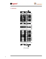
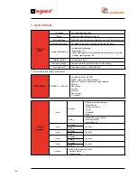
The images of the different main frame pages are given below.
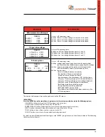
MAIN PAGE
DATA DISPLAYED
1 Input – output – battery
1st line: UPS operating status;
2nd line: Input voltages;
3rd line: Voltage set in output, active power absorbed by the load
and total load applied percentage
4th line: Bar showing residual battery capacity and actual time
of operation in the case of a power failure.
2 Input – percentage output – battery
1st line: UPS operating status;
2nd line: Input voltages;
3rd line: Load percentage on the phases in output;
4th line: Bar showing residual battery capacity and actual time
of operation in the case of a power failure.
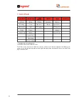
3 Bypass – output – battery
1st line: UPS operating status;
2nd line: Bypass voltages;
3rd line: Voltage set in output, active power absorbed by the load
and total load applied percentage
4th line: Bar showing residual battery capacity and actual time
of operation in the case of a power failure.
4 Bypass – percentage output – battery
1st line: UPS operating status;
2nd line: Bypass voltages;
3rd line: Load percentage on the phases in output;
4th line: Bar showing residual battery capacity and actual time
of operation in the case of a power failure
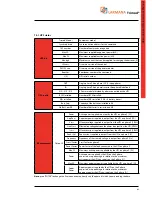
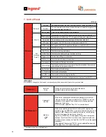
5 Load availability in output
1st line: UPS operating status;
2nd line: Phase L1: power in kVA or Watt with respect to nominal power
or current with respect to the nominal and relative percentage;
3rd line: Phase L2: power in kVA or Watt with respect to nominal power
or current with respect to the nominal and relative percentage;
4th line: Phase L3: power in kVA or Watt with respect to nominal power
or current with respect to the nominal and relative percentage
6 Measurements on the output
1st line: UPS operating status;
2nd line: Phase L1 in output: Voltage, current and active power;
3rd line: Phase L2 in output: Voltage, current and active power;
4th line: Phase L3 in output: Voltage, current and active power.
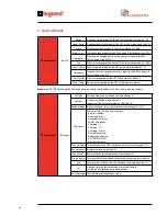
7 Output related voltages
1st line: UPS operating status;
2nd line: output: line voltage between phases L1 and L2;
3rd line: output: line voltage between phases L2 and L3;
4th line: output: line voltage between phases L3 and L1
75,02'
%<3
Ȝ
999
287
%DWWK
75,02'
/R
N9$
/R
N9$
/R
N9$
75,02'
/R9
$
:
/R9
$
:
/R9
$
:
75,02'
/R/R
U
9
/R/R
U
9
/R/R
U
9
75,02'
,1
Ȝ
999
287
%DWWK
75,02'
%<3
Ȝ
999
287
Ȝ
9:
%DWWK
75,02'
,1
Ȝ
999
287
Ȝ
9:
%DWWK
7. Control Panel
Содержание Trimod 10 kVA
Страница 1: ...Trimod Operating and Maintenance Manual Part LE05768AA 07 12 01 GF ...
Страница 2: ... 2 EN ENGLISH 3 Trimod ...
Страница 12: ...12 UPS Trimod 10 UPS Trimod 10 15 20 2 3 Models 2 Technological description ...
Страница 13: ...Trimod Operating and Maintenance Manual 13 UPS Trimod 10 15 20 UPS Trimod 30 TT ...
Страница 14: ...14 UPS Trimod 30 TM UPS Trimod 40 2 Technological description ...
Страница 15: ...Trimod Operating and Maintenance Manual 15 UPS Trimod 60 ...
Страница 16: ...16 2 Technological description UPS Trimod BATTERY UPS Trimod BATTERY 2 ...
Страница 42: ...42 5 Installation UPS Trimod 30TM ...
Страница 43: ...Trimod Operating and Maintenance Manual 43 UPS Trimod 30TT ...
Страница 44: ...44 UPS Trimod 40 60 5 Installation ...
Страница 46: ...46 5 Installation ...


