background image

18

®

3 104 36

10 kVA

3 104 37

15 kVA

3 104 37

20 kVA

3 104 39

30 kVA TM

3 104 38

30 kVA TT

3 104 40

40 kVA

3 104 41

60 kVA

Type of batteries

12V 7.2Ah or 12V 9Ah maintenance-free sealed lead batteries

Tolerated overload

125% per 2 min – 150% per 30 s

Batteries

3 104 36

10 kVA

3 104 37

15 kVA

3 104 37

20 kVA

3 104 39

30 kVA TM

3 104 38

30 kVA TT

3 104 40

40 kVA

3 104 41

60 kVA

Bypass

Automatic (static and electromechanical)

Manual (for maintenance)
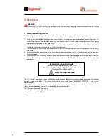
Signals and alarms

Large alphanumerical display with 4 lines,  

multicolored status indicator, buzzer

Communication ports

Two RS 232 ports, 1 relay interface, 1 contact port

Software

Can be downloaded free of charge from the web site www.ups.legrand.com

Protections

Electronic against overloads, short-circuits and excessive battery discharging.

Functions blocks if autonomy ends.  

Powering surge limiter.

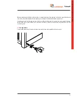
E.P.O. contact (total shutdown in an emergency) BackFeed Protection.

3 104 36

10 kVA

3 104 37

15 kVA

3 104 37

20 kVA

3 104 39

30 kVA TM

3 104 38

30 kVA TT

3 104 40

40 kVA

3 104 41

60 kVA

Net weight UPS (without batteries)

110 Kg

130 Kg

154 Kg

Dimensions UPS (L x H x D) (mm)

414 x 1367 x 628

3400VA Power modules installed

3

5000VA Power modules installed

3

6

6

6700VA Power modules installed

3

6

9

Power modules - Net weight

8 Kg

Battery drawing - Net Weight

14 Kg

3 104 36

10 kVA

3 104 37

15 kVA

3 104 37

20 kVA

3 104 39

30 kVA TM

3 104 38

30 kVA TT

3 104 40

40 kVA

3 104 41

60 kVA

Operating temperature

0°C ÷ 40°C

Relative humidity

20% ÷ 80% non-condensing

Noise level at 1m

58 ÷ 62 dBA

Grade of protection

IP 21

Accessories

Mechanical characteristics

Environmental conditions

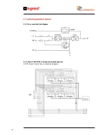
2. Technological description

Содержание Trimod 10 kVA

Страница 1: ...Trimod Operating and Maintenance Manual Part LE05768AA 07 12 01 GF ...

Страница 2: ... 2 EN ENGLISH 3 Trimod ...

Страница 3: ... Level Interface 21 2 4 4 Communications slot 21 2 4 5 Power module block diagram 22 2 4 6 Interconnection block diagram 22 3 Safety provisions 23 3 1 General notes 23 3 2 Symbols 23 3 3 Definitions of operator and specialized technician 23 3 3 1 Qualification required to the operator 23 3 3 2 Qualification required to the specialized technician 24 3 4 Individual protective gear 24 3 4 1 Gear to w...

Страница 4: ...1 Safety reccomandations 35 5 2 2 Preliminary operations 35 5 2 3 Connectiong the loads 35 5 2 4 Emergency Power Off Remote E P O 36 5 2 5 Installing the Trimod BATTERY 36 5 2 6 Protections 39 5 2 7 Earthing 39 5 2 8 Connectiong the power supply 39 5 2 9 Wiring 40 5 3 Wiring diagrams 40 5 3 1 THREE PHASE input THREE PHASE output 41 5 3 2 THREE PHASE input SINGLE PHASE output output connections 45 ...

Страница 5: ... output phases ON and OFF 70 7 2 8 Shutting down the UPS Trimod 70 8 Diagnostics 71 8 1 Luminous and acoustic signals 71 8 2 Messagges 73 9 Maintenance 80 9 1 Introduction 80 9 2 Preventive maintenance 80 9 3 Periodical checks 80 9 3 1 Preparing the UPS for maintenance Forced bypass mode 80 9 4 Adding or replacing a power module or battery drawers 81 9 4 1 Power Module 81 9 4 2 Exit from the maint...

Страница 6: ...ctricity The persons to whom this publication is addressed normally defined users are all those people who for their field of expertise have the need and or obligation to provide instructions or work directly on the equipment These people can be the following managers heads of operating areas department heads operators directly concerned with transporting storing installing using and servicing mac...

Страница 7: ... fitting to send to the users must be kept with the manual becoming an integral part of it 1 5 Collaboration with the user The Manufacturer is available to its clientele to provide additional information and will take into consideration any suggestions made to improve this manual to bring it even closer to the requirements for which it was drawn up If the equipment is sold which always includes ha...

Страница 8: ...icable If the equipment is sold to a thirty party in a country of a different language it is the responsibility of the original user to provide a true translation of this manual in the language of the country where the equipment is going to be used 1 8 Copyright The information in this manual must not be disclosed to third parties Any duplication total or partial not authorised in writing by the M...

Страница 9: ...unctions The modularity philosophy has also been used for the batteries which are supplied in single pull out boxes THDi 3 Power Factor 0 99 High Yield High Reliability Easy to install and service 2 2 Features Redundant modular architecture Redundant modular architecture is the best way to protect a company s critical points Advantages There is just one control of the devices powered Modular Expan...

Страница 10: ...designed for easy insertion in the cabinet with no work needed to connect them they are easy to handle thanks to their light weight likewise any maintenance or replacing A box holds 5 12V 7 2 Ah or 9 Ah batteries connected in series and thanks to the Plug Play connection can be easily pulled out and put inside the cabinet In order to guarantee maximum safety especially during maintenance the volta...

Страница 11: ... output frequency are the same as the network input and the UPS Trimod can not control these variables The benefit that you get in the Off Line mode is greater electrical efficiency since UPS doesn t work If the output voltage goes out of tolerance range 15 of the set voltage output or is lacking the UPS activates its stage inverter powering the load with the energy stored in the batteries The run...

Страница 12: ...12 UPS Trimod 10 UPS Trimod 10 15 20 2 3 Models 2 Technological description ...

Страница 13: ...Trimod Operating and Maintenance Manual 13 UPS Trimod 10 15 20 UPS Trimod 30 TT ...

Страница 14: ...14 UPS Trimod 30 TM UPS Trimod 40 2 Technological description ...

Страница 15: ...Trimod Operating and Maintenance Manual 15 UPS Trimod 60 ...

Страница 16: ...16 2 Technological description UPS Trimod BATTERY UPS Trimod BATTERY 2 ...

Страница 17: ...5 A 27 8 A 37 A 55 5 A Maximum current Single phase Three phase 55 5 A 83 3 A 111 A 166 5 A Maximum current Single phase Single phase 55 5 A 83 3 A 111 A 166 5 A Input voltage 230 V 15 20 Single phase 400 V 15 20 Three phase Neutral line is essential 400 V 15 20 Three phase Neutral line is essential Input frequency 50 60 Hz Power factor on the input 0 99 THD input current 3 Input 310436 10kVA 3104...

Страница 18: ...ic against overloads short circuits and excessive battery discharging Functions blocks if autonomy ends Powering surge limiter E P O contact total shutdown in an emergency BackFeed Protection 310436 10kVA 310437 15kVA 310437 20kVA 310439 30kVATM 310438 30kVATT 310440 40kVA 310441 60kVA Net weight UPS without batteries 110 Kg 130 Kg 154 Kg Dimensions UPS L x H x D mm 414 x 1367 x 628 3400VA Power m...

Страница 19: ... 42 46 dBA Grade of protection IP 20 IEC 529 OUTPUT Maintenance voltage 13 75 Vdc battery Rated current max 15 Adc AC DC Efficiency 93 at max rated current INDICATIONS Operating mode multi color LED on the module and display menu information on the UPS Yellow LED Fast intermittent f1 recharge fase Green LED Slow intermittent f2 recharge fase and maintenance Green LED fi xed stand by Red LED Fault ...

Страница 20: ...second called user interface is at the top at the back of the UPS Thanks to this port that with either a computer or specific network card it is possible to access UPS operating data and to control the unattended turning off of the operating system 2 4 2 Relay interface E P O The default setting of the relay interface contacts is Normally Open NO but can be configured as Normally Closed NC via the...

Страница 21: ...ower supply Pin 6 do not connect Pin 7 Overload open collector active low Pin 12 UPS on Battery open collector active low Pin 13 UPS on Bypass open collector active low Pin 14 Autonomy Reserve open collector active low Pin 15 Alarm open collector active low Electrical specifications Logic output 12VDC max output impedance 2 2kΩ in series RS232 power supply 12VDC 700mA max not adjusted Open collect...

Страница 22: ...22 2 4 5 Power module block diagram 2 4 6 Trimod 30KVA TM Interconnection block diagram All UPS Trimod models have a similar block diagram 2 Technological description ...

Страница 23: ...personnel who know how to use and service the equipment and have the following requirements 1 Specific training that authorises them to work according to the safety standards in relation to the dangers that the presence of electricity can bring about 2 Training on how to use the Individual Protective Devices and on the basic first aid interventions When the company person in charge of safety choos...

Страница 24: ...ion of company risks in accordance with the European Directive 89 391 EEC safety at the work place in ITALY it is part of the Law Decree dated 12 11 1994 The person in charge of safety must ensure that all people working on the machine have received all the relevant instructions of this manual included start up and commissioning and with particular reference to the contents of this chapter 3 4 Ind...

Страница 25: ...le and cleaned periodically If a plate is ruined and or is no longer legible even only in part ask for a new one from the Manufacturer who is bound to supply a substitute WARNING The plates must be neither removed nor covered it is forbidden to affix others on the equipment without the prior written authorisation from the Manufacturer 3 6 Residual risks Residual risks are risks that were impossibl...

Страница 26: ... trained personnel Do not deactivate the safety devices or delude the indications alarms and warnings whether they are communicated automatically or by means of plates on the installation Do not turn the machine on without the fixed protections in place panels etc In the case of breakages deformation or malfunctions of the equipment or parts of it repair or replace immediately avoiding emergency r...

Страница 27: ...nsult the laws existing in the country where the equipment is installed 3 8 1 First aid interventions If any first aid intervention is required comply with company rules and traditional procedures 3 8 2 Fire prevention measures Do not use water to extinguish fire but only the extinguishers designed specifically for putting fires out on electronic equipment ...

Страница 28: ...s The technical legal documentation that comes with the equipment includes the user manual for the specific type of UPS to install together with the CE Declaration of Conformity In the case of defects and or material missing send a report immediately to the Manufacturer and wait for his instructions before commissioning the equipment 4 2 Unpacking To remove the packing material observes the ARROW ...

Страница 29: ...ust be on dry clean and fresh premises where the ambient temperature is between 0 C and 50 C 32 122 F and with humidity below 90 not condensing 4 4 2 Batteries The standard batteries of the UPS Trimod are sealed lead acid they are maintenance free and installed internally Lead is a dangerous substance for the environment if it is not recycled by specialized companies If the batteries are not charg...

Страница 30: ...umidity and temperature must be within the prescribed limits the fire protection regulations must be observed wiring must be of easy execution the front and rear must be accessible for assistance or routine maintenance the flow of cooling air must be guaranteed the air conditioned system must be adequately sized there must be no corrosive explosive gases the premises must be free from vibrations t...

Страница 31: ... enough for the aforementioned requirements If maintenance work has to be done on parts that are insufficiently illuminated it is compulsory to use portable lighting being careful not to create shadows that will prevent or reduce visibility on the point you are working on or on the surrounding areas 4 7 Last operations Once positioned correctly fit the two side base strips and the front one suppli...

Страница 32: ...circuit protection against return voltage must be provided externally to the UPS backfeed protection See diagrams on the next page 5 You will have to affix a warning label on all power disconnects the power supply placed away from the UPS in order to alert the service personnel that the circuit is connected to a UPS The label must contain the following text or equivalent Before working on this cir...

Страница 33: ...ree Phase Configuration 5 1 1 Mains connection and Backfeed protection drawings for TN systems In the diagrams S1 is the circuit breaker required S3 is bypass line breaker contact S4 are backfeed protection circuit contacts Three Phase Three Phase Configuration Three Phase Single Phase Configuration ...

Страница 34: ...S3 is input line breaker contact S4 are backfeed protection circuit contacts WARNING In case of Backfeed Protection warning please contact Technical Support Single Phase Single Phase Configuration Single Phase Three Phase Configuration Three Phase Three Phase Configuration Three Phase Single Phase Configuration 5 Installation ...

Страница 35: ...ou will find the terminal block on which to do the connections 5 2 2 Preliminary operations Before connecting the UPS make sure that 1 Mains voltage volt V in input and frequency correspond to the values on the UPS rating plate 2 Earthing complies with the IEC standards International Electronic Commission or local regulations 3 The electrical system is equipped with all the necessary differential ...

Страница 36: ...ied There are four different external battery cabinets for the Trimod BATTERY units a modular model consisting of a cabinet with an internal structure that uses battery drawers for up to a maximum of 80 12V 7 2Ah or 12V 9Ah batteries 16 drawers a modular model consisting of a cabinet with an internal structure that uses battery boxes for up to a maximum of 100 12V 7 2Ah or 12V 9Ah batteries 20 dra...

Страница 37: ...Y to the UPSTrimod must be done according to the following diagram and the steps listed below 1 Make sure that all the battery fuse carrier isolating switches are open 2 Connect the UPS and the additional battery cabinet using the earth cable yellow green 3 Use the wiring supplied with the Trimod BATTERY to connect the positive and negative terminals of the UPS Trimod to those of the Trimod BATTER...

Страница 38: ...en 2 In each Trimod BATTERY remove the lower front panel 3 In each Trimod BATTERY remove the terminal block loosening the 2 securing screws 4 Connect the UPS and the additional battery cabinet using the earth cable yellow green 5 Use the wirings supplied with theTrimod BATTERY to connect the positive and negative terminals of the UPSTrimod to those of the Trimod BATTERY 5 Installation UPS Trimod 4...

Страница 39: ...e EARTH terminal on the UPS terminal block INDICATION The wiring diagrams are given in the DIAGRAMS chapter 5 2 8 Connecting the power supply For safety reasons connection of the power supply must be the last thing to be done Before connecting the power supply cables with input make sure that the maintenance by pass S1 is open in the OFF position and arrange fuses and jumpers on the terminal block...

Страница 40: ...s The fairleads are supplied in the accessories kit The plate is fixed to the UPS with four screws 5 3 Wiring diagrams The electrical configuration can be set up either on the operator panel or on the terminal block of the distribution box located inside at the bottom of the front door To access the distribution terminal block you have to loosen the box locking screws and pull it outwards WARNING ...

Страница 41: ...HASE output The UPS is dispatched with the connections as per the following diagram To use it with this configuration no interventions are required We do however suggest that you check beforehand that the wiring in input output and the connection of the modular terminals is correct UPS Trimod 10 15 20 ...

Страница 42: ...42 5 Installation UPS Trimod 30TM ...

Страница 43: ...Trimod Operating and Maintenance Manual 43 UPS Trimod 30TT ...

Страница 44: ...44 UPS Trimod 40 60 5 Installation ...

Страница 45: ... plug in all the Back Panel cards in the connector supplied in the accessory kit The Back Panel cards are located inside the machine behind the power modules There is only one Back Panel card in the Trimod 10 15 20 models while in the Trimod 30TM there are two To access the Back Panel cards and insert the connector simply extract 3 power modules that are on the same shelf and refer to the followin...

Страница 46: ...46 5 Installation ...

Страница 47: ...the software has to be configured via the instrument panel as illustrated in paragraph 6 4 STARTING PROCEDURE ATTENTION If the UPS is used with a single phase output available on 10 15 20 30TM models you will have to plug in all the Back Panel cards in the connector supplied in the accessory kit Follow the instructions given in the previous paragraph UPS Trimod 10 15 20 30TM ...

Страница 48: ... and three phase output configuration the manual by pass S1 MUST NOT be activated for any reason whatsoever To this end the relative switch must be locked in the OFF position For greater safety it is possible to deactivate the by pass completely by cutting the brown cable that connects the relative by pass switch S1 to the MAINS INPUT fuse carrier isolating switch isolating it To the contrary the ...

Страница 49: ... PHASE input connection no 3 separate outputs For this type of connection besides the wiring shown in the following figure the software has to be configured via the instrument panel as illustrated in paragraph 6 4 STARTING PROCEDURE UPS Trimod 10 15 20 30TM ...

Страница 50: ...r to get the required length Insert the cross connector into modular terminals as shown in connection blocks Insert the cross connector into modular terminals as shown in connection blocks Secure the cross connector to modular terminal with all the provided screws 5 Installation ...

Страница 51: ...Trimod Operating and Maintenance Manual 51 Screw all cross connectors Remove the plastic cover Check all cross connectors have been screwed properly Insert the plastic cover ...

Страница 52: ...52 5 3 6 UPS Trimod 30TM connections To properly connect the UPS Trimod 30TM it is necessary to remove both panels illustrated in the following figures 5 Installation ...

Страница 53: ... select management of the three phases as follows THREE single phase outputs this setting is necessary if three separate single phase lines were created at the UPS output In this case the UPS manages the three outputs separately one from the other For example if an excessive load is applied to one of the three output lines the bypass will intervene only on the overloaded line while power is guaran...

Страница 54: ...e phase 120 Three separate phases depending on the connection Use the arrow keys to move the selection on the display the Enter key to confirm the ESC key to cancel Note The configuration of the inverter output that is selected by display three or single phase must strictly correspond to the setup on the output terminals during installation WARNING Wrong connections or output configuration setting...

Страница 55: ...oad Otherwise enter the required values 12 Close the output switch of the UPS At this stage the load is powered and protected by the UPS Trimod WARNING If when installing you think it is necessary to check that the battery run UPS is working properly turn the mains power voltage OFF by means of the switch breaker outside the UPS and NOT by means of the input breakers inside the UPS distribution dr...

Страница 56: ...e main menu and return to displaying status Silencing the acoustic indicator 3 UP ARROW key Main functions Selects the previous function Increases a value inside a function Selects a new item inside a function e g from ENABLED to DISABLED Scrolls the menus that contain more than 4 lines Changes the main frame page 4 DOWN ARROW key Main functions Selects the next function Reduces a value inside a f...

Страница 57: ...e strings displayed Italian English German French Russian Spanish Polish and Portuguese To exit this mode press the ON OFF key otherwise after 20 minutes without receiving any manual or serial commands the UPS exits the function automatically and shuts down 7 2 Main menu and Submenus Press the ON OFF button to start the UPS and confirm with the ENTER key when prompted At the end of the start up pr...

Страница 58: ... in output 4th line Bar showing residual battery capacity and actual time of operation in the case of a power failure 5 Load availability in output 1st line UPS operating status 2nd line Phase L1 power in kVA or Watt with respect to nominal power or current with respect to the nominal and relative percentage 3rd line Phase L2 power in kVA or Watt with respect to nominal power or current with respe...

Страница 59: ...e current and active power 4th line Phase L3 in input Voltage current and active power 9 Bypass line voltages 1st line UPS operating status 2nd bypass line line voltage between phases L1 and L2 3rd bypass line line voltage between phases L2 and L3 4th bypass line line voltage between phases L3 and L1 10 Battery status 1st line UPS operating status 2nd line voltage load current negative value with ...

Страница 60: ...on the right of the display when there are other items to see Use the arrow keys to see these items UPS STATUS UPS SETTINGS POWER MODULES EVENTS TOOLS LOG OUT o UPS Info Options PM status Visualization Batteries UPS config Output Diagnostics Deletion Signalling Test Measurements Input PM SW update LCD DisplayTest Alarms Bypass Support Historical Data Batteries Reset CM Errors Operator Panel Clock ...

Страница 61: ...utput from the UPS on phase X A RMS Peak I Val Peak current supplied in output from the UPS on phase X A Frequency Frequency of the sinusoid voltage in output from phase X Hz Crest I Factor Crest factor on phase X Power Factor Power factor of the load connected to the UPS on phase X Max W Maximum active power suppliable by the UPS on phase X W Power Active power supplied by the UPS on the X phase ...

Страница 62: ...tage measured at the ends of the batteries V Current Current supplied by the batteries negative if the batteries are being charged A ResidualCapac Battery charged status expressed as a percentage 0 100 Chg Status Working status of the battery charger Batt in Standby Running down Autonomy reserve End of autonomy Charging f1 Charging f2 Charging maint Batt being tested Battery equalisation BATTERIES...

Страница 63: ... has been working Tot run downs Total number of times the batteries have been completely run down Booster Int Total number of Booster interventions Bypass Int Total number of Bypass interventions Batt Calibr Total number of battery Calibrations Battery ch Cycles Total number of battery charger cycles Batt eq cycles Total number of battery equalisation cycles 80 load N Total number of times the loa...

Страница 64: ...with the input and is signalled by the flashing of the status indicator green PLL range Allows you to select the frequency range in which the UPS synchronizes output voltage with input voltage NORMAL UPS synchronizes to the frequency variations of 2 of the nominal value EXTENDED UPS synchronizes to the frequency variations of 14 of the nominal value CUSTOM set by user see main menu Extended PLL ra...

Страница 65: ...ormal uses FAST loads sensitive to the microinterruptions Start with Bypass If enabled when the mains are switched on the first load feeding by the UPS is via the bypass If disabled the load peak will be handled by the inverter as happens when switching on with the battery Batteries Threshold Values Aut end warning Setting the start time of the end of battery autonomy warning Max Battery time Sett...

Страница 66: ...settings Password level The default setting is in the USER item Clock Setting DD MM YY HH mm SS Set the date time of the UPS ENTER selects the value to change ARROWS increases reduces the value selected DD day MM month YY year HH hour mm minutes SS seconds Only available with the password chosen Contact Interface Item 1 Function It allows to set item function Mains Battery Autonomy reserve Alarm O...

Страница 67: ...z for the bypass line Crest I Factor Crest factor applied by the power module X to the mains Power factor Power factor applied by the power module X to the mains Output X Power Active power supplied by the power module X W Appar Power ApparentpowersuppliedinoutputbythepowermoduleX VA V rms Effective voltage supplied in output by the power module X V RMS Linked Vrms Line voltage in output by the po...

Страница 68: ...erloads Total number of overloads No HV Bus run Total number of overvoltages on the Bus No Out DC Level Total number of continuous voltage presences in output from the PMs 7 Control Panel INDICATION Press ENTER to change the X value and consequently vary the power module from where you read data Diagnostics Reset PM Errors Deletes the memory of errors found in the power module Resets only resettab...

Страница 69: ...ng out this cycle so that the UPS provides precise information about the charge status Battery cycle Executes a Battery Test and battery equalisation to verify their status and performance and to maximise battery life Support Display Code Displays code to communicate to Technical Service Use Code Insert code supplied by Technical Service Reset CM Errors Deletes the memory of errors found in comman...

Страница 70: ...TION The shutting down procedure described below is to be used only and exclusively if the load applied to the UPS is off or does not need powering by it 1 Check there is no need to power the connected loads 2 Hold down the ON OFF button on the UPS control panel for at least 2 seconds 3 When asked Turn the UPS off confirm with the ENTER key 4 Wait for the shutdown operation to finish If the UPS ne...

Страница 71: ...3 independent phases output GREEN Fixed 1 module ORANGE Fixed The remaining modules GREEN Fixed Battery equalisation Batteries being equalised GREEN Fastintermittent GREEN Fastintermittent There is no mains voltage and or incorrect mains frequency on at least one module 68Hz or 43Hz and or the input PLL is not synchronised GREEN Fastintermittent No bypass input PLL is not synchronised bypass volta...

Страница 72: ...ction HVBUS connection RED Fastintermittent Fast intermittent BATTERIES K O Batteries failed or not connected RED Fast intermittent RED Short double blink with pause Fast intermittent RUNAWAY BATTERIES Excessive voltage on the batteries RED Fast intermittent RED Short double blink with pause Fast intermittent HVBUS RUNAWAY FAILURE Excessive voltage on the high voltage DC buses RED Fast intermitten...

Страница 73: ...ctly by the mains via a manual bypass In this configuration the load is not protected by the UPS UPS OFF LINE The load is powered directly by the bypass line The load is protected because if there is a power failure with the line it switches the load over to battery UPS ON BATTERY UPS on battery The cause for this configuration is a failure in the UPS feeding system or a mains power failure BATTER...

Страница 74: ...must be either repaired or changed LOAD OFF An excessive load e g short circuit has caused an excessive drop in the output voltage for too long a time or the load has been switched off due to a prolonged battery overload UPS IN EMERGENCY UPS in Emergency UPS STOPPED UPS has stopped Shutdown in progress The unit is shutting down because it was programmed by the user PM not updated The software of o...

Страница 75: ...e not compatible with the UPS Call assistance Start up error An error occurred during start up of the UPS Start up interrupted Start up possible only by confirming Start up was not confirmed within 30 seconds UPS shut down by programming UPS shut down by programming Shutting down due to an incorrect configuration An error occurred in configuration UPS in shutting down The number of Power Modules d...

Страница 76: ...ication system with the Power Modules Emergency Emergency Load not powered Power to the loads has been interrupted Abnormal shutting down UPS shut down abnormally Shutting down due to an overload UPS shut down due to an prolonged overload Shutting down due to an Emergency Power Off UPS shut down due to an Emergency Power Off Batteries KO Battery failure PM battery connection failure Failure in the...

Страница 77: ...he number of Power Modules installed on the UPS has changed Shutting down due to incorrect configuration UPS shutting down due to an incorrect configuration The number of Power Modules detected by the UPS is incorrect for the output configuration set Power Module FW update The Power Module Firmware updated Big overload Big overload Feeding from the output Voltage present on the UPS output Check co...

Страница 78: ...attery test executed Battery test completed successfully Batteries calibrated Batteries calibrated successfully Forced bypass ON The forced bypass mode has been enabled The load is powered by force directly by the bypass Load not protected Forced bypass OFF The forced bypass mode has been disabled Maintenance bypass ON The load is powered directly by the manual bypass disconnector Load not protect...

Страница 79: ... Power Modules BATTERY CONNECTION FAILURE Error in connecting the battery to the Power Module Check the connection and the battery fuse inside the Power Module MAINS CONNECTION FAILURE Error in connecting the mains to the Power Module Check the connection and the mains fuse inside the Power Module H V BUS CONNECTION FAILURE Error in connecting the D C Bus to the Power Module Check the connection a...

Страница 80: ...roblems contact the LEGRAND assistance centre immediately 9 3 Periodical checks Correct operation of the UPS must be guaranteed by periodical maintenance inspections essential for safeguarding the unit s operating life and reliability WARNING The periodical checks entail operations inside the UPS where dangerous voltages are present Only maintenance personnel trained and authorised by LEGRAND know...

Страница 81: ...dling the module If they are on wait until they have turned off 3 Verify that on the new power module the two LEDs visible through the holes are both OFF If ON wait for them to go OFF 4 Put the new power module in the same place of the old one or in one of the available compartments if you wish to increase UPS power 5 Secure the power module to the unit s frame with the 2 screws provided The proce...

Страница 82: ...d secure them with the screws provided 5 Repeat steps 2 3 and 4 for each KB to install replace In the case of simple addition of KB is enough to follow the steps 2 4 and 5 WARNING Always replace only 1 KB at a time Note If the UPS switches to battery while you are performing the operation stop and do not remove or insert battery drawers it is possible to resume operation when the UPS returns to wo...

Страница 83: ...remove and dismantle the unit wear the Individual Protective Gear described in chapter 3 and refer to the instructions and charts that you will find in this manual Once the various parts have been removed divide the components into groups separating metal from plastic from copper etc according to the selected disposal scheme used in the country where the unit is being dismantled If the parts have ...

Страница 84: ...TABLE 1 Minimal Recommended Cable Sections for UPS Trimod TABLE 2 UPS Trimod Recommended Battery Fuse Ratings 11 Tables POWER INPUT PHASES OUTPUT PHASES INPUT CABLE OUTPUT CABLE 10 kVA 3 3 5 x 4 mm2 5 x 4 mm2 1 1 3 x 10 mm2 3 x 10 mm2 1 3 3 x 10 mm2 5 x 4 mm2 3 1 5 x 10 mm2 3 x 10 mm2 15 20 kVA 3 3 5 x 10 mm2 5 x 10 mm2 1 1 3 x 25 mm2 3 x 25 mm2 1 3 3 x 25 mm2 5 x 10 mm2 3 1 5 x 25 mm2 3 x 25 mm2 ...

Страница 85: ... 4 50A 500V gG 14 x 51 N 4 50A 500V gG 14 x 51 POWER BATTERY FUSE Trimod BATTERY 2 5KB F B F B 10 15 20 30 40 60 kVA N 5 50A 500V gG 14 x 51 N 5 50A 500V gG 14 x 51 POWER BATTERY FUSE Trimod BATTERY 1x94Ah F B F B 10 kVA N 1 50A 500V gG 22 x 58 N 1 50A 500V gG 22 x 58 15 20 kVA N 1 100A 500V gG 22 x 58 N 1 100A 500V gG 22 x 58 30 kVA TT TM N 2 80A 500V gG 22 x 58 N 2 80A 500V gG 22 x 58 40 kVA N 2...

Страница 86: ... curve C 3φ 1 φ 100A 1P N curve C 1φ 1 3 φ 20 kVA 40A 3P N curve C 3φ 3 φ 100A 3P N curve C 3φ 1 φ 100A 1P N curve C 1φ 1 3 φ 30 kVA TM 63A 3P N curve C 3φ 3 φ 160A 3P N curve C 3φ 1 φ 160A 1P N curve C 1φ 1 3 φ 30 kVA TT 63A 3P N curve C 3φ 3 φ 40 kVA 80A 3P N curve C 3φ 3 φ 60 kVA 100A 3P N curve C 3φ 3 φ POWER DIFFERENTIAL BREAKER DIFFERENTIAL CURRENT 10 kVA 300 mA B type 15 kVA 300 mA B type 2...

Страница 87: ...ed Cable Sections POWER BATTERY CURRENT MINIMAL RECOMMENDED CABLE SECTION 10 kVA 44A 1 x 10 mm2 for each pole 15 kVA 66A 1 x 16 mm2 for each pole 20 kVA 88A 1 x 25 mm2 for each pole 30 kVA TT TM 132A 1 x 50 mm2 for each pole 40 kVA 176A 2 x 25 mm2 for each pole 60 kVA 264A 2 x 50 mm2 for each pole ...

Страница 88: ...5 LIMOGES CEDEX FRANCE 33 5 55 06 87 87 Fax 33 5 55 06 74 55 www legrandelectric com Installer stamp Legrand reserves at any time the right to modify the contents of this booklet and to communicate in any form and modality the changes brought to the same ...

Отзывы: