


Trimod®
Oper
ating and M
ain
tenanc
e M
anual
45
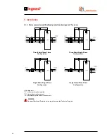
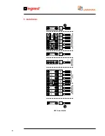
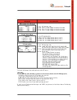
5.3.2 THREE-PHASE input, SINGLE-PHASE output connection
For this type of connection, besides the wiring shown in the following figure, the software has to be configured via the
instrument panel as illustrated in paragraph 6.4 STARTING PROCEDURE.
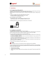
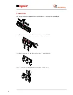
ATTENTION
If the UPS is used with a single-phase output (available on 10/15/20/30TM models) you will have to plug in all the
‘Back Panel’ cards in the connector supplied in the accessory kit.
The ‘Back Panel’ cards are located inside the machine behind the power modules.
There is only one ‘Back Panel’ card in the Trimod® 10/15/20 models while in the Trimod® 30TM there are two. To
access the ‘Back Panel’ cards and insert the connector, simply extract 3 power modules that are on the same shelf
and refer to the following figure. The connector must be inserted in the position indicated with EC 15 on the card
serigraphy. To extract the power modules please consult the MAINTENANCE chapter.
UPS Trimod
®
10/15/20/30TM
Содержание Trimod 10 kVA
Страница 1: ...Trimod Operating and Maintenance Manual Part LE05768AA 07 12 01 GF ...
Страница 2: ... 2 EN ENGLISH 3 Trimod ...
Страница 12: ...12 UPS Trimod 10 UPS Trimod 10 15 20 2 3 Models 2 Technological description ...
Страница 13: ...Trimod Operating and Maintenance Manual 13 UPS Trimod 10 15 20 UPS Trimod 30 TT ...
Страница 14: ...14 UPS Trimod 30 TM UPS Trimod 40 2 Technological description ...
Страница 15: ...Trimod Operating and Maintenance Manual 15 UPS Trimod 60 ...
Страница 16: ...16 2 Technological description UPS Trimod BATTERY UPS Trimod BATTERY 2 ...
Страница 42: ...42 5 Installation UPS Trimod 30TM ...
Страница 43: ...Trimod Operating and Maintenance Manual 43 UPS Trimod 30TT ...
Страница 44: ...44 UPS Trimod 40 60 5 Installation ...
Страница 46: ...46 5 Installation ...


