


36
®
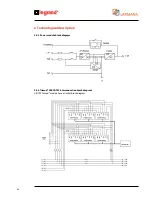
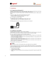
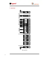
5.2.4 Emergency Power Off (Remote E.P.O.)
In accordance with the standards, the UPS is fitted with an emergency device that uses a normally closed contact (already
installed on the UPS) that can be opened to activate the emergency machine power off.
The E.P.O. terminals are in the UPS’s rear panel on pins 3 and 4 of the 6-pole Combicon connector installed on contact
interface.
To connect the emergency power off device please follow these instructions:
- Use a cable with double insulation, no more than 10 metres in length.
- Check that the switch used is galvanically insulated.
Electrical specifications of the E.P.O. interface:
- Voltage between terminals 3 and 4 (6P Combicon) with open circuit = 12Vdc.
- Current between terminals 3 and 4 (6P Combicon) with closed circuit = 5mA
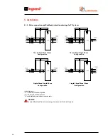
The following figure shows how the emergency power off device has to be connected.
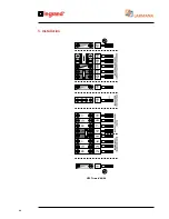
5.2.5 Installing the Trimod® BATTERY
It is possible to connect external battery units to increase ups autonomy.
If the configuration uses more than one battery it is necessary to position all the Trimod® Battery units on the same side
of the UPS Trimod® and connect them in cascade with each other using the multicore cables supplied.
There are four different external battery cabinets for the Trimod® BATTERY units:
- a modular model consisting of a cabinet with an internal structure that uses battery drawers for up to a maximum of 80
12V 7.2Ah or 12V 9Ah batteries (16 drawers).
- a modular model consisting of a cabinet with an internal structure that uses battery boxes for up to a maximum of 100
12V 7.2Ah or 12V 9Ah batteries (20 drawers).
- a compact, non modular, economical model that uses a shelf architecture instead and on which the batteries are
placed. It can house 60 or 120 12V 7.2Ah or 12V 9Ah batteries.
- a compact, non modular, economical model that uses a shelf architecture instead and on which the batteries are
placed. It can house 20 12V 94Ah batteries.
A Trimod® BATTERY can be connected to several UPS Trimod® units.
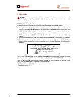
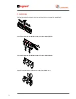
WARNING
The following instructions are of a prescriptive nature and it is imperative they be complied with.
Opening or removing the panels from the UPS Trimod® or Trimod® BATTERY you risk exposure to high and dangerous
voltages! To guarantee protection of personnel during installation of the Trimod® BATTERY make sure that the connections
are done under the following conditions:
1. There must be no mains voltage
2. The loads are off and disconnected;
3. The UPS Trimod® is off with no voltage and all fuse carrier isolating switches on the UPS Trimod® and Trimod® BATTERY
are open.
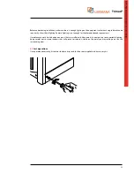
5. Installation
Содержание Trimod 10 kVA
Страница 1: ...Trimod Operating and Maintenance Manual Part LE05768AA 07 12 01 GF ...
Страница 2: ... 2 EN ENGLISH 3 Trimod ...
Страница 12: ...12 UPS Trimod 10 UPS Trimod 10 15 20 2 3 Models 2 Technological description ...
Страница 13: ...Trimod Operating and Maintenance Manual 13 UPS Trimod 10 15 20 UPS Trimod 30 TT ...
Страница 14: ...14 UPS Trimod 30 TM UPS Trimod 40 2 Technological description ...
Страница 15: ...Trimod Operating and Maintenance Manual 15 UPS Trimod 60 ...
Страница 16: ...16 2 Technological description UPS Trimod BATTERY UPS Trimod BATTERY 2 ...
Страница 42: ...42 5 Installation UPS Trimod 30TM ...
Страница 43: ...Trimod Operating and Maintenance Manual 43 UPS Trimod 30TT ...
Страница 44: ...44 UPS Trimod 40 60 5 Installation ...
Страница 46: ...46 5 Installation ...


