


48
®
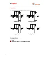
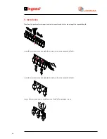
5.3.4 SINGLE-PHASE input, THREE-PHASE 120° output connection
For this type of connection, besides the wiring shown in the following figure, the software has to be configured via the
instrument panel as illustrated in paragraph 6.4 STARTING PROCEDURE.
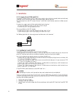
WARNING
In the Trimod® models 10, 15, 20 and 30TM, in the case of a single-phase input and three-phase output configuration,
the manual by-pass S1 MUST NOT be activated for any reason whatsoever. To this end the relative switch must be
locked in the ‘OFF’ position. For greater safety it is possible to deactivate the by-pass completely by cutting the brown
cable that connects the relative by-pass switch S1 to the MAINS INPUT fuse carrier isolating switch, isolating it. To the
contrary, the cable connecting terminal 8 to the phase fuse carrier isolating switch MUST remain connected.
5. Installation
UPS Trimod® 10/15/20/30TM
Содержание Trimod 10 kVA
Страница 1: ...Trimod Operating and Maintenance Manual Part LE05768AA 07 12 01 GF ...
Страница 2: ... 2 EN ENGLISH 3 Trimod ...
Страница 12: ...12 UPS Trimod 10 UPS Trimod 10 15 20 2 3 Models 2 Technological description ...
Страница 13: ...Trimod Operating and Maintenance Manual 13 UPS Trimod 10 15 20 UPS Trimod 30 TT ...
Страница 14: ...14 UPS Trimod 30 TM UPS Trimod 40 2 Technological description ...
Страница 15: ...Trimod Operating and Maintenance Manual 15 UPS Trimod 60 ...
Страница 16: ...16 2 Technological description UPS Trimod BATTERY UPS Trimod BATTERY 2 ...
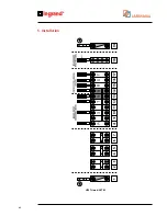
Страница 42: ...42 5 Installation UPS Trimod 30TM ...
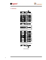
Страница 43: ...Trimod Operating and Maintenance Manual 43 UPS Trimod 30TT ...
Страница 44: ...44 UPS Trimod 40 60 5 Installation ...
Страница 46: ...46 5 Installation ...


