


3-2
HVM100 User Manual
4/11/03
The ICP
®
setting will provide a 28 Volt 2mA constant cur-
rent to each of the three input channels, in order to power up
to three accelerometers. This is used with ICP
®
type acceler-
ometers. The voltage reported on this screen is a monitoring
of the ICP
®
power being provided to the transducer. When
the transducer is not connected, this voltage will read 25 to
26 volts. If you have a transducer connected and it is work-
ing properly, it should be reading between 2 and 12 volts
depending upon the transducer.
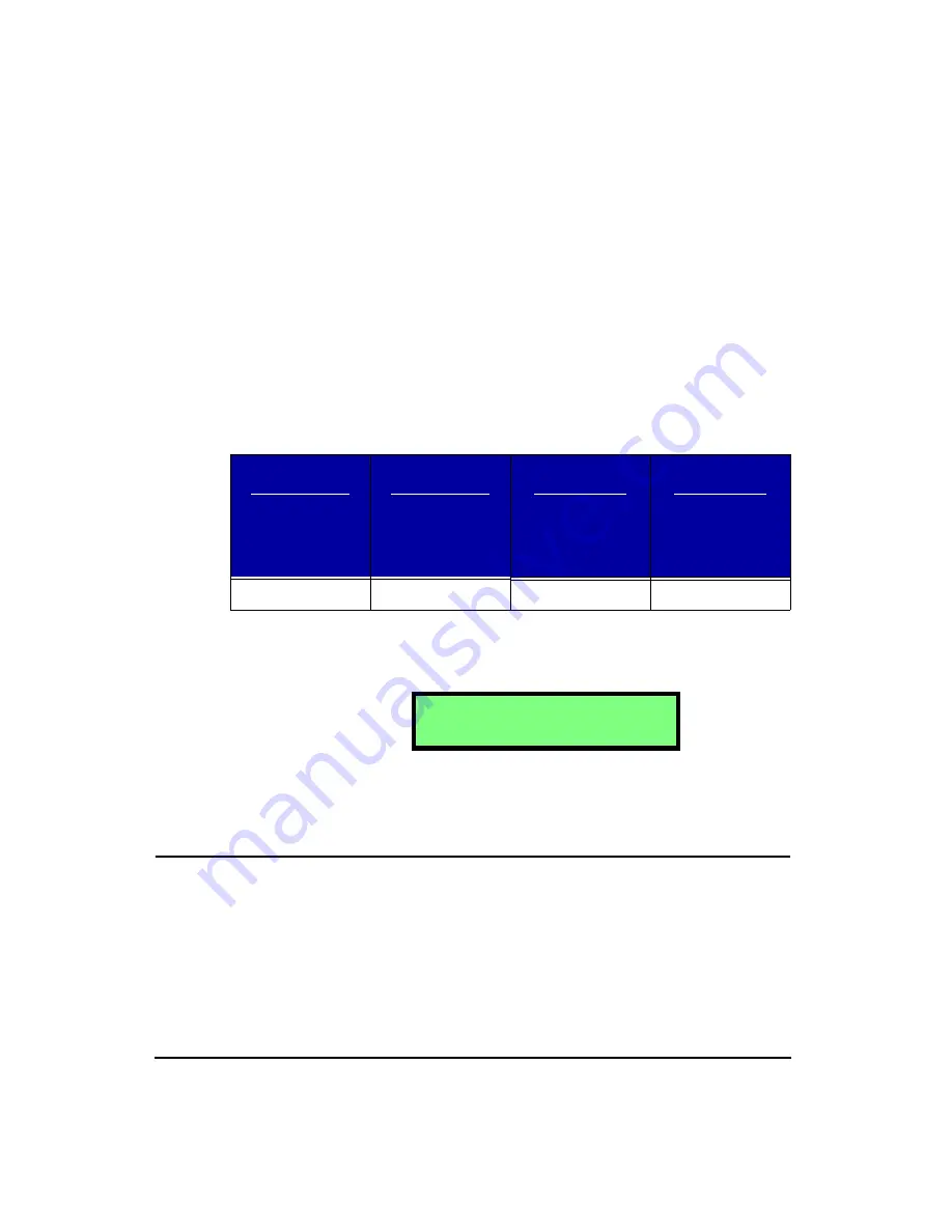
The following table shows the typical bias voltage for the
various ICP accelerometers that are nornally used with the
HVM100.
If the reading is 0, then the ICP
®
power could be shorted to
ground or have some other problem. Check all connections,
cables, and connectors.
This setting would be used to amplify the signal from a
charge type accelerometer.
Display Units
Hint:
This setting is in the Tools menu. To access the Tools menu press the
TOOLS
key and then use the
u
and
d
arrow keys to navigate
through the menu items.
NOTE: To view each selection, first press
the
c
key, and then press the
r
or
l
arrow key to scroll through each selec-
tion.
The Display Units setting controls how data is displayed and
printed by the HVM100. The HVM100 can display data in
six different formats. The selection of the display units will
apply to all three channels and the sum channel. All chan-
Tri-Axial
Accelerometers
SEN020
SEN021
SEN021F
SEN022
Single Axis
Accelerometers
SEN023
SEN024
SEN025
Palm-Adapter
Accelerometer
SEN026
Seat Pad
Accelerometer
SEN027
8-12 volts
8-12 volts
7-11 volts
2-5 volts
A c c e l e r o m e t e r
C h a r g e
Содержание HVM100
Страница 8: ...HVM100 User Manual 6...
Страница 18: ...1 10 HVM100 User Manual 4 11 03...
Страница 29: ...4 11 03 Getting Started 2 11 Weighting X Wk...
Страница 30: ...2 12 HVM100 User Manual 4 11 03...
Страница 44: ...3 14 HVM100 User Manual 4 11 03...
Страница 50: ...4 6 HVM100 User Manual 4 11 03...
Страница 55: ...4 11 03 Printing 5 5 Step 5 Select Hyperterminal from the menu A new con nection dialog box will appear...
Страница 56: ...5 6 HVM100 User Manual 4 11 03 Step 6 Enter a name and choose an icon for your Hyper terminal connection...
Страница 57: ...4 11 03 Printing 5 7 Step 7 Press the OK button...
Страница 58: ...5 8 HVM100 User Manual 4 11 03 Step 8 The Connect to dialog box will appear...
Страница 62: ...5 12 HVM100 User Manual 4 11 03 Left click the Properties button Properties Settings...
Страница 63: ...4 11 03 Printing 5 13 Left click the Settings Tab at the top of the window to open the Setting dialog box...
Страница 67: ...4 11 03 Printing 5 17...
Страница 68: ...5 18 HVM100 User Manual 4 11 03...
Страница 80: ...6 12 HVM100 User Manual 4 11 03...
Страница 93: ...4 11 03 Powering the HVM100 8 5 The connector pinout is as follows Negative Positive Positive Negative...
Страница 94: ...8 6 HVM100 User Manual 4 11 03...
Страница 102: ...9 8 HVM100 User Manual 4 11 03...
Страница 146: ...D 2 HVM100 User Manual 4 11 03...
Страница 147: ...4 11 03 D 3...
Страница 148: ...D 4 HVM100 User Manual 4 11 03...
Страница 149: ...4 11 03 D 5...
Страница 150: ...D 6 HVM100 User Manual 4 11 03...
Страница 151: ...4 11 03 D 7...
Страница 152: ...D 8 HVM100 User Manual 4 11 03...
Страница 153: ...4 11 03 D 9...
Страница 154: ...D 10 HVM100 User Manual 4 11 03...
Страница 155: ...4 11 03 D 11...
Страница 156: ...D 12 HVM100 User Manual 4 11 03...
Страница 157: ...4 11 03 D 13...
Страница 158: ...D 14 HVM100 User Manual 4 11 03...
Страница 170: ...F 4 Warranty Customer Satisfaction April 11 2003...
Страница 174: ...HVM100 User Manual 4...


