


E-4
HVM100 User Manual
4/11/03
The DC output is tied directly to the rms, min, max, and
peak values measured by the HVM100; therefore, the DC
output signal is not available if the instrument has been
RESET. If the instrument is in a RESET condition, the DC
output level will be at approximately -300 mV.
The DC output range covers the entire measurement range
of the HVM100. In other words, the DC output signal level
is not affected by the gain settings.
AC Output
The maximum signal produced by the AC output is approxi-
mately 0.5 Vrms. However, the maximum input level mea-
surable by the HVM100 is approximately 5.0 Vrms (a
difference of 20 dB). Therefore, in order for the HVM100’s
AC output to function properly with each range (i.e. gain
settings of 0, 20, 40, and 60 dB), the HVM100’s gain set-
tings also affect the AC output signals. For example, with a
gain setting of 0 dB, the HVM100 can measure input signals
as large as 5.0 Vrms. Since these signals exceed the AC out-
put range, they are attenuated to 0.5 Vrms (a gain of -20 dB)
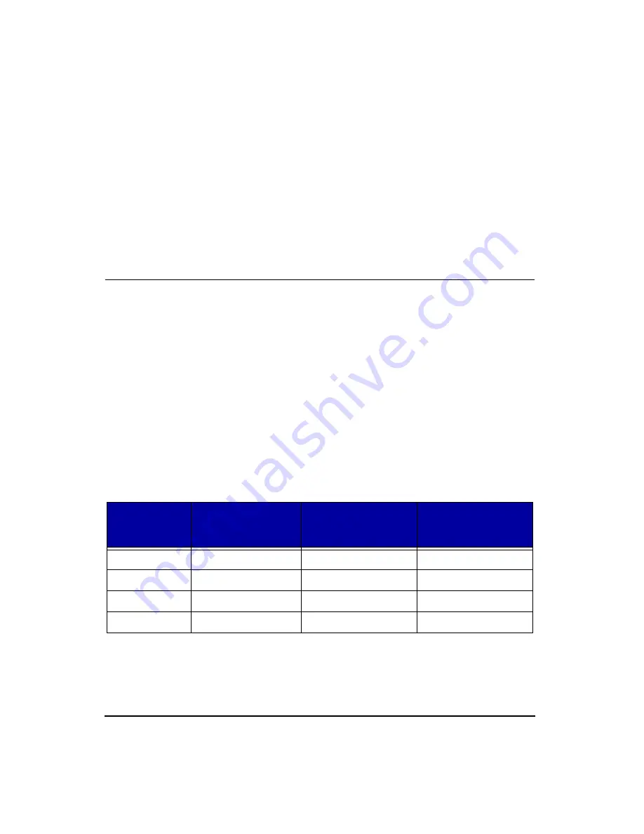
so that they can be reproduced by the AC output. The table
below shows the correlation between input signal level and
AC output signal level.
AC Output Gain
RANGE
(Gain Setting)
INPUT
Maximum Signal
Level (Vrms)
AC OUTPUT Gain
AC OUTPUT
Maximum Signal Level
(Vrms)
0 dB
5.0
-20 dB
0.5 Vrms
20 dB
0.5
0 dB
0.5 Vrms
40 dB
0.05
+20 dB
0.5 Vrms
60 dB
0.005
+40 dB
0.5 Vrms
Содержание HVM100
Страница 8: ...HVM100 User Manual 6...
Страница 18: ...1 10 HVM100 User Manual 4 11 03...
Страница 29: ...4 11 03 Getting Started 2 11 Weighting X Wk...
Страница 30: ...2 12 HVM100 User Manual 4 11 03...
Страница 44: ...3 14 HVM100 User Manual 4 11 03...
Страница 50: ...4 6 HVM100 User Manual 4 11 03...
Страница 55: ...4 11 03 Printing 5 5 Step 5 Select Hyperterminal from the menu A new con nection dialog box will appear...
Страница 56: ...5 6 HVM100 User Manual 4 11 03 Step 6 Enter a name and choose an icon for your Hyper terminal connection...
Страница 57: ...4 11 03 Printing 5 7 Step 7 Press the OK button...
Страница 58: ...5 8 HVM100 User Manual 4 11 03 Step 8 The Connect to dialog box will appear...
Страница 62: ...5 12 HVM100 User Manual 4 11 03 Left click the Properties button Properties Settings...
Страница 63: ...4 11 03 Printing 5 13 Left click the Settings Tab at the top of the window to open the Setting dialog box...
Страница 67: ...4 11 03 Printing 5 17...
Страница 68: ...5 18 HVM100 User Manual 4 11 03...
Страница 80: ...6 12 HVM100 User Manual 4 11 03...
Страница 93: ...4 11 03 Powering the HVM100 8 5 The connector pinout is as follows Negative Positive Positive Negative...
Страница 94: ...8 6 HVM100 User Manual 4 11 03...
Страница 102: ...9 8 HVM100 User Manual 4 11 03...
Страница 146: ...D 2 HVM100 User Manual 4 11 03...
Страница 147: ...4 11 03 D 3...
Страница 148: ...D 4 HVM100 User Manual 4 11 03...
Страница 149: ...4 11 03 D 5...
Страница 150: ...D 6 HVM100 User Manual 4 11 03...
Страница 151: ...4 11 03 D 7...
Страница 152: ...D 8 HVM100 User Manual 4 11 03...
Страница 153: ...4 11 03 D 9...
Страница 154: ...D 10 HVM100 User Manual 4 11 03...
Страница 155: ...4 11 03 D 11...
Страница 156: ...D 12 HVM100 User Manual 4 11 03...
Страница 157: ...4 11 03 D 13...
Страница 158: ...D 14 HVM100 User Manual 4 11 03...
Страница 170: ...F 4 Warranty Customer Satisfaction April 11 2003...
Страница 174: ...HVM100 User Manual 4...


