background image

17

DATA MANAGEMENT

Update Brands/Flavors

1.  Using the 

Tower Brand Management Software

, create the 

necessary 

.brand

 file, complete with new brand name and 

images.


Any data imported to the TsT will completely replace 


all existing content. For example: If the user wishes to 


add new brands to the existing brands library, the user 


must upload both the existing brand file as well as the 


new brand file(s). 


For information on the Tower Brand Management 


Software visit lancercorp.com, contact your Lancer 

Customer Service Representative. Visit lancercorp.com 

and access the Tower Brand Management Software 

Instruction Sheet (Lancer Part Number: 28-2855/01).

IMPORTANT

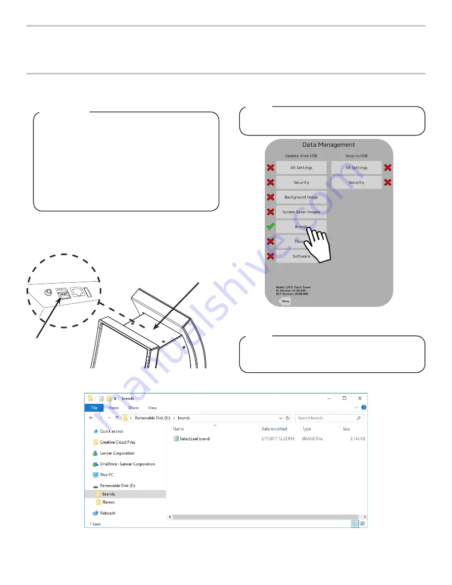
4.  From the Service Menu, press the 

Data Management 

button. 

5.  In the “Update from USB” section, press the 

Brands

 button. 


There will be a check mark next to the Brands button if 

the USB drive has the brand files in the correct place.

NOTE


To upload new flavors to the TsT User Interface,  


create the flavor 

.brand

 file and put into a folder named 

“flavors”, then repeat steps 2-5. 

NOTE

6.  Once the Brands button turns green then the updated brands 

will be available.

2.  Create a USB drive with the created 

.brand

 file in a folder 

named “brands” as shown in the image below. 

3.  Plug the USB into the Tower port located underneath the top 

plate of the tower (See page 8). 

A. USB Port (Underneath Top Plate)

B. Top Plate

A

B

Содержание CoCo Fountain Tower

Страница 1: ...k of Lancer 2018 by Lancer all rights reserved Lancer Corporation 6655 Lancer Blvd San Antonio Texas 78219 800 729 1500 Tech Support Warranty 800 729 1550 email custserv lancercorp com web lancercorp com Lancer PN 28 3012 Revision August 2018 Operation Manual ...

Страница 2: ... THIS UNIT This manual contains important safety information and all applicable safety precautions must be observed To reduce the risk of fire electric shock damage to the equipment or personal injury when using this unit all instructions warnings on the product being used must be followed Text following the Attention signal addresses a situation that if not followed could potentially damage the e...

Страница 3: ...tenance The resettable breaker switch should not be used as a substitute for unplugging the dispenser from the power source to service the unit Only qualified personnel should service internal components of electrical control housing WARNING Make sure that all water lines are tight and units are dry before making any electrical connections If this dispenser is installed in an area that is suscepti...

Страница 4: ...psi 0 137 MPa Max Static Pressure 65 psi 0 448 MPa CARBON DIOXIDE CO2 SUPPLY Min Pressure 70 psi 0 483 MPa Max Pressure 80 psi 0 552 MPa FITTINGS Carb Water Inlet 3 8 inch 9 5 mm barb Carb Water Outlet 3 8 inch 9 5 mm barb Plain Water Inlet 3 8 inch 9 5 mm barb Brand Syrup Inlets 3 8 inch 9 5 mm barb Drain Fitting 5 8 inch 15 9 mm barb Specifications Features PRE INSTALLATION 26 9 in 17 1 in 2 1 i...

Страница 5: ...ocation of Drain Location of Electrical Outlet Location of Heating and Air Conditioning Ducts Do you have enough space to install the dispenser Is counter top level Can the counter top support the weight of the dispenser Is dispenser located away from direct sunlight or overhead lighting TOOLS REQUIRED Oetiker Pliers Tubing Cutters Wrench Slotted Screwdriver Phillips Screwdriver Drill Refractomete...

Страница 6: ... should be no more than 48 if touch point is less than 10 from the front of the counter or a maximum of 46 if the touch point is more than 10 and less than 27 from the front of the counter For more information about the customer s legal requirements for the accessibility of installed equipment refer to 2010 ADA Standards for Accessible Design http www ada gov NOTE 2 Select a location that utilizes...

Страница 7: ... the return inlet 5 Slide drip tray into opening in tower until magnets engage and lock drip tray in place Connect ADA wire harness from drip tray to ADA wire harness in tower NSF listed units must be sealed to the counter NOTE A D E F C B A Seal B Drip Tray C Counter D Upper Drain Fitting E Lower Drain Fitting F Washer 7 Plug in power cord to power supply then route power supply cord to the desig...

Страница 8: ...swift fluid motion slide your finger in a clockwise direction around the outer edge of the pour button The dispenser must be properly electrically grounded to avoid serious injury or fatal electrical shock The power cord has a three prong grounded plug If a three hole grounded electrical outlet is not available use an approved method to ground the unit Follow all local electrical codes when making...

Страница 9: ...dules can be purged at one time Once four modules are selected all other modules are greyed out and cannot be selected NOTE 19 Once a steady flow of water is achieved press the Purge button again to deactivate the modules 20 Ensure that the pump deck at the remote chiller is turned off before turning on the CO2 21 Turn on CO2 at the source then using a screwdriver adjust the high pressure regulato...

Страница 10: ...r left side of the screen A Configure Tab D Brand Water Type B Configure Button E Brand Ratio C Activated Module A B C D E 9 Select a new brand from the available Brands Library tabs on the left side of the screen 8 Press the Configure button under any of the activated brand or flavor modules to open its Configuration Page Each brand has a default water type and ratio already set when they are sel...

Страница 11: ... of 5 seconds A Enter Flow Rate C Start Purge Button B Timer Icon D Unit Icon A B C D 7 Place an empty cup on a gram scale with at least a 0 1 resolution and tare the cup 8 Once the scale is tared position the empty cup under the nozzle and press the Start Purge button The unit will dispense for 5 seconds 9 Place the cup with water on the scale and weigh the sample If the weight is not between 210...

Страница 12: ...value between 3 8 4 2 then use a screwdriver to adjust the brand syrup flow control accordingly See Plumbing Diagram on page 27 for reference 7 Repeat steps 3 5 until a Brix value of 3 8 4 2 is achieved 8 Repeat steps 2 6 for the remaining brand syrup modules 9 Press the Maintenance button to return to the Maintenance screen and then press the Menu button to return to the Service menu The water fl...

Страница 13: ...nitizing section of this manual Every Six Months Clean remote chiller according to manufacturer s instructions if necessary Clean the entire exterior of the unit Time Delay Features FEATURES OF THE TOUCHSCREEN TOWER 1 From the Service Menu press the Time Delays button to access the Time Delays Menu 2 Update the current Date Time if necessary by tapping the field and using the keypad to enter the c...

Страница 14: ...if available B A A Enable Nutrition B Custom Background C Volume Unit D Time Format 3 Press the Menu button to return to the Service Menu and press the Save Settings and Exit button to return to the Main Screen 5 Access the Service menu and press the System button to return to the System menu 6 Enable the Custom background function to use the new background image uploaded from a USB drive if avail...

Страница 15: ...sing and when the unit is not dispensing Idle 3 Below the Nozzle Light sliders the user can change how the ribbon lights on the side of the dispenser are displayed Spectrum Ribbon lights cycle through preset colors The brightness and the speed at which the colors cycle can be adjusted using the sliders One Color Ribbon lights are displayed using only one color determined by the user Press the Colo...

Страница 16: ...on the far left side of the screen 3 From here manually adjust specific brands to read Ready Out or Auto This feature will automatically shut off the pump for that specific brand when there is no product to be dispensed This feature only comes into effect when the corresponding brand is changed to Auto in the Sold Out menu NOTE A Sold Out Sensors Tab B Sold Out Sensors 1 10 C SO3 Enabled for Brand...

Страница 17: ... Management Software Instruction Sheet Lancer Part Number 28 2855 01 IMPORTANT 4 From the Service Menu press the Data Management button 5 In the Update from USB section press the Brands button There will be a check mark next to the Brands button if the USB drive has the brand files in the correct place NOTE To upload new flavors to the TsT User Interface create the flavor brand file and put into a...

Страница 18: ...the USB drive has the video and text files in the correct place NOTE 2 Create a txt file in any editor software ex Notepad on Windows machines that contains the name of the video file and is named list txt as shown in the image below 3 Once both the video file and list txt file are in the ss folder on the USB Drive plug in the drive into the Tower port located underneath the head of the tower 4 Fr...

Страница 19: ...spenser DO NOT spill sanitizing solution on any circuit boards Insure all sanitizing solution is removed from the system ATTENTION Export Tower Settings Update Background Image 1 Plug an empty USB Drive into the Tower port located underneath the head of the tower 2 Access the Service Menu and under the Save to USB section press the All Settings button 1 Create a USB Drive with the new video file i...

Страница 20: ...lution clean the nozzle injectors 7 Using a soft clean cloth sanitize the nozzle injectors and let air dry 8 Reconnect nozzle 9 Connect power 10 Taste the drink to verify that there is no off taste If off taste is found sanitize the nozzle and nozzle injectors again 3 Rinse nozzle with warm water Following sanitization rinse with end use product until there is no aftertaste Do not use a fresh wate...

Страница 21: ...ssure to BIB pumps 2 Out of CO2 3 Shutoff on mounting block not fully open 4 Foreign debris in syrup flow control 5 Bad syrup pump 1 Adjust CO2 pressure to 80 PSI 0 550 MPa minimum 70 PSI 0 480 MPa for BIB pumps 2 Replace CO2 tank refill 3 Open shutoff fully 4 Remove syrup flow control form upper body and clean out any foreign material to ensure smooth free spool movement 5 Replace BIB pump Errati...

Страница 22: ... ice 8 High beverage temperature 1 Correct prior to dispenser Consider larger dispenser or pre cooler 2 Adjust CO2 pressure downward but not less than 70 PSI 0 483 MPa 3 Re adjust and reset ratio Refer to Adjust Water Flow Rate Syrup Water Ratio Section 4 Remove and reinstall properly 5 Remove nozzle and clean injectors 6 Bleed air from BIB lines 7 Check quality of ice used in drink 8 Check refrig...

Страница 23: ...1 BIB connector not on tight 2 BIB connector is stopped up 3 Kinks in syrup line 4 Bad BIB Pumps 1 Tighten BIB connector 2 Clean out or replace BIB connector 3 Straighten or replace line 4 Replace BIB pump BIB pump fails to restart when dispensing valve is closed 1 Leak in discharge line or fittings 2 Empty BIB 3 Air leak on inlet line or bag connector 1 Repair or replace discharge 2 Replace BIB 3...

Страница 24: ...19 x 0 437 05 05 3434 01 Drip Tray Bumper Left 06 05 3432 01 Drip Tray Bumper Right 07 05 3295 01 Front Cosmetic Panel 08 05 3294 01 Front Internal Panel 09 30 16121 Mounting Plate Bracket TsT 10 30 11888 Center Panel Left 11 30 11889 Center Panel Right 12 04 1714 Washer M4 13 04 1717 Nut M4 14 04 1689 01 Screw M4 15 30 11890 Center Panel Top 16 05 3437 Lower Rear Cover 17 05 3292 01 Rear Internal...

Страница 25: ...iffuser CW TsT 07 05 3297 02 Nozzle Mount TsT 08 10 2003 Nozzle Pin Mach CW TsT 09 05 4019 Nozzle Plug Mach CW TsT 10 17 2000 Check Lee Valve 11 04 1621 Screw 4 20 X 0 38 SS PT 12 05 4023 Inner Nozzle Body Mach CW TsT 13 02 0214 01 O Ring 2 008 97 1114 14 05 4022 Nozzle Fitting Mach CW TsT 15 05 3309 Water Inlet Locking Clip 16 04 1511 Screw 4 20X 375 PHD PH SL PL 17 05 1385 Elbow 5 Dole 18 19 100...

Страница 26: ...sy 05 12 0629 Keypad Membrane Switch 06 52 3718 Harness Keypad to ADA 07 04 1709 01 Hex Nut M3 x 0 5 SS 08 04 1716 Washer Flat M3 09 10 0958 Magnet Neo 0 5 X 0 125 10 04 1748 Screw M3 11 02 0681 Washer 0 343 OD X 0 093 12 10 1000 Magnet Neo Reverse 0 5 X 0 125 13 64 5061 PCB Assy Valve Board 14 64 5104 01 PCB Assy Power Board 15 05 3483 Front Lens Left 16 05 3486 Rear Lens Left 17 52 3730 LED Stri...

Страница 27: ...7 Unit Plumbing Diagram S7 S8 SD PW S9 RC S10 SD PW S7 S8 S9 S10 Item Description S7 Syrup Line 7 S8 Syrup Line 8 S9 Syrup Line 9 S10 Syrup Line 10 PW Plain Water Line SD Soda Line RC Recirculation Line ...

Страница 28: ...28 Unit Wiring Diagram ...

Страница 29: ...29 Counter Cut out To Scale 1 62 41 28 5 02 127 49 4 13 101 71 6 19 157 30 CUT ALONG DOTTED LINES FRONT OF UNIT ...

Страница 30: ...Lancer Corp 800 729 1500 Technical Support Warranty 800 729 1550 custserv lancercorp com lancercorp com ...

Отзывы: