


61
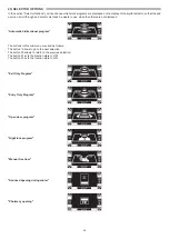
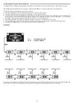
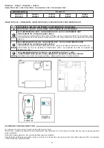
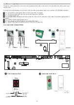
30) INTERLOCK SYSTEM
The interlock system is used to connect two automatic doors when a door can open only if the other one is closed.
For the electrical connection between the control units ET‑LOGIC‑B of the two automations, a UR24 module (optional) is required for
each control unit. Couple the module UR24 in the connector J2‑OUT1 of the control unit ET‑LOGIC‑B.
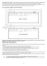
30.1) ELECTRICAL CONNECTION FOR INTERLOCK
The purpose of the dotted line related to the ON/OFF switch connected to the input AUX/1 is to be able to disable the interlock
operation (connection not essential to the operation of the system).
Switch OFF (open contact): interlock ON
Switch ON (contact closed): interlock OFF.
The above diagram shows the electrical connection between the automations of the two doors ensuring that they are interlocked during
operation.
•
Terminal 19 (COM) of control unit 1 must be connected to terminal C of its UR24 module.
•
The N.O. terminal of the UR24 module of control unit 1 must be connected to terminal 14 (STOP/I) of control unit 2.
•
Terminal 19 (COM) of control unit 2 must be connected to terminal C of its UR24 module.
•
The N.O. terminal of the UR24 module of control unit 2 must be connected to terminal 14 (STOP/I) of control unit 1.
•
Both terminals 19 (COM) of each control unit must be connected together.
•
The interlock input (terminal 14) must be configured as N.C. (function F24= OFF).
If you wish to by‑pass the interlock operation and allow the two doors to operate independently, you need to connect an ON / OFF switch
in parallel between terminals 16 (AUX1) and 19 (Common) of both automation control units.
This way when the switch contact is open the interlock is enabled, while when the switch contact is closed the interlock is disabled and
the two automatic doors can operate independently.
To enable interlocked operation you need to install the digital selector ET-DSEL as program selector.
You cannot use the EV‑MSEL mechanical key selector.
DOOR 1 ET-LOGIC-B
DOOR 2 ET-LOGIC-B
ON/OFF
SWITCH


