


19
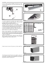
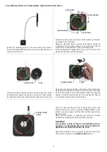
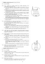
10.4) INSTALLATION OF THE MANUAL RELEASE ON THE WALL
Identify the fastening point on the wall, taking into account
that the standard cable sheath is 3 metre long and that it must
reach the electric lock.
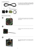
Thread the release cable in the slit in the base and then inside
the adjustment register as shown in the figure. Then position
the cable terminal on the release handle cable lock (see figure).
Drill the wall and secure the bottom of the release mechanism
by means of the setscrews.
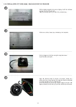
Apply the adhesive label as shown in the figure, taking as
a reference the four black bands on the label that must be
positioned in correspondence of the 4 cardinal points.
Insert the adjustment register with 2 nuts, one in the slot of the
plastic and the other outside the same.
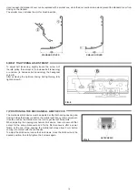
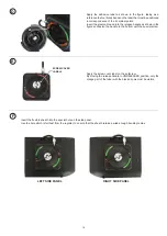
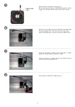
Now, insert the release handle on the base of the mechanism,
being careful to keep the cable terminal in the seat of the cable
lock and the handle in the correct position. When inserting the
handle, the cable terminal must be in the position just beyond
(in clockwise direction) the lower setscrew.
Once you have inserted the knob, fix the setscrew, insert the
sheath and turn the knob to position UNRELEASED. In this
position, only the orange part of the label with the black arrows
must be visible.
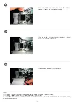
Make sure the system is operating by turning the handle
clockwise and keeping the cable taut with your hand.
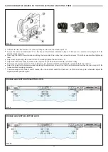
WARNING!:
THE HANDLE TURNS BY MAX 45-50 DEGREES AND AT
THE END, IT IS PROVIDED WITH CATCHES IN ORDER TO
MAINTAIN THE POSITION AFTER THE LOCK.
Apply the provided screw cover label as shown in the figure
and return the handle to the
UNRELEASED
position.
SETSCREW
CABLE LOCK
LOWER SCREW
SETSCREW
BLACK BANDS
LUGS
SCREW COVER
LABEL
LUGS
BLACK BANDS