


35
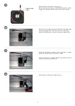
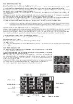
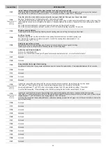
17) SAFETY SENSORS
This paragraph describes the procedure to be followed to properly connect and set-up some of the safety sensors available on the
market and complying with the EN12978 standard, to ensure a safety level which complies with PL=c - Cat. 2, as provided for by the
standard EN16005.
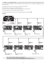
17.1) SENSOR OA-AXIS T / OA-FLEX T
Application as activation and closing safety sensor
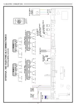
WIRING OF SENSOR OA-AXIS T / OA-FLEX T
ETERNA 150 AUTOMATION ET-LOGIC-B TERMINAL BOARD
Correspondence between the sensor cables and the terminal board of the automation ETERNA 150 of the control unit ET-LOGIC-B
1. WHITE
(+)
Power supply
TERMINAL 22 (+)
2. BROWN
(‑)
Power supply
TERMINAL 21 (‑)
3. GREEN
N.O.
(activation)
TERMINAL 12 (Internal radar) or 13 (External radar)
4. YELLOW
COM
TERMINAL 10 COMMON
5. PINK +
Opto NPN (sensor 1 safety)
TERMINAL 5 E.C.1 Closing safety sensor 1
PINK +
Opto NPN (sensor 2 safety)
TERMINAL 6 E.C.2 Closing safety sensor 2
6. BLUE ‑
COM
(sensor 1 safety)
TERMINAL 7 COMMON
BLUE ‑
COM
(sensor 2 safety)
TERMINAL 7 COMMON
7. RED
(+)
Test
TERMINAL 20 TEST (+)
8. BLACK
(‑)
Test
TERMINAL 21 (‑)
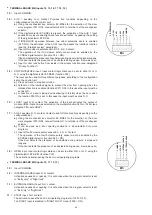
OA-AXIS T DIP SWITCH SETTINGS
DIP 10 = OFF
Automatic control enabled
DIP 11 = OFF
Output High
DIP 12 = ON
Test input Low
For information about the adjustments and the other functional
settings of the sensor, please refer to the instructions supplied
with the sensor.
OAM-DUAL TE DIP SWITCH SETTINGS
DIP 7 = OFF
Output High
DIP 8 = ON
Test input Low
DIP 14 = OFF
Self-monitoring enabled
For information about the adjustments and the other functional
settings of the sensor, please refer to the instructions supplied
with the OAM‑DUAL TE sensor.
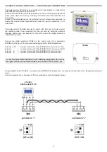
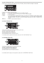
FUNCTIONAL SETTINGS OF SELECTOR ET-DSEL
F12 (S05) = ON
If the safety sensor is installed on E.C.1
F13 (S06) = ON
If the safety sensor is installed on E.C.2
F16 (S09) = ON
Closing safety sensors test enabled
F18 (S11) = OFF
Test level LOW
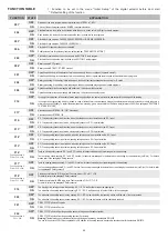
FUNCTIONAL SETTINGS OF SELECTOR ET-DSEL
F12 (S05) = ON
If the safety sensor is installed on E.C.1
F13 (S06) = ON
If the safety sensor is installed on E.C.2
F16 (S09) = ON
Closing safety sensors test enabled
F18 (S11) = OFF
Test level LOW
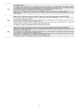
17.2) SENSOR OAM-DUAL TE
Application as activation and closing safety sensor
OAM-DUAL TE SENSOR WIRING
ETERNA 150 AUTOMATION ET-LOGIC-B TERMINAL BOARD
Correspondence between the sensor cables and the terminal board of the automation ETERNA 150 of the control unit ET-LOGIC-B
1. WHITE
Power supply
TERMINAL 22 (+)
2. BROWN
Power supply
TERMINAL 21 (‑)
3. GREEN
Actuation (relay)
TERMINAL 12 (Internal radar) or 13 (External radar)
4. YELLOW
Actuation (relay)
TERMINAL 10 COMMON
5. PINK
Safety sensor 1
TERMINAL 5 E.C.1 Closing safety sensor 1
PINK
Safety sensor 2
TERMINAL 6 E.C.2 Closing safety sensor 2
6. BLUE
Safety sensor 1
TERMINAL 7 COMMON
BLUE
Safety sensor 2
TERMINAL 7 COMMON
7. RED
(+)
Test
TERMINAL 20 TEST (+)
8. BLACK
(‑)
Test
TERMINAL 21 (‑)
9. GREY / PINK (+)
Actuation for escape routes
NOT USED
10. RED/BLUE
(‑)
Actuation for escape routes
NOT USED


