7
G
A
a
b
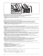
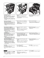
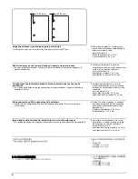
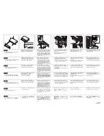
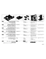
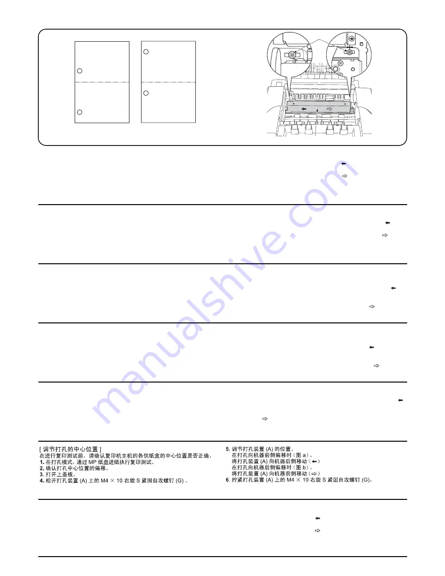
Centering punch-holes
Confirm the center position of each drawer in the copier is correct. Per-
form the following steps to adjust the punch holes.
1.
In the punch mode, perform a test copy with paper fed from the MP
tray.
2.
Check for any off-centering in the punch holes.
3.
Open the upper cover.
4.
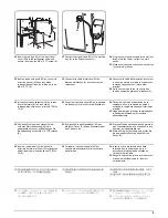
Loosen two M4
×
10 Tap Tight S screws (G) of the punch unit (A).
5.
Adjust the position of the punch unit A.
When holes are punched too far forward (figure “a”)
Slide the punch unit A to the machine rear ( ).
When holes are punched too far backward (figure “b”)
Slide the punch unit A to the machine front ( ).
6.
Tighten two M4
×
10 Tap Tight S scres (G) of the punch unit (A).
Centrer les perforations
Vérifier que chaque tiroir du copieur est parfaitement centré. Respecter
la procédure suivante pour régler les perforations.
1.
En mode perforation, effectuer une copie de test en définissant
l’alimentation papier sur le plateau multifonction.
2.
Vérifier qu’il n’existe pas de décalage dans les perforations.
3.
Ouvrir le couvercle supérieur.
4.
Desserrer deux vis S taraudées M4
×
10 (G) de l’unité de perforation (A).
5.
Régler la position de l’unité de perforation A.
Lorsque les perforations sont trop avancées (figure “a”)
Faire glisser l’unité de perforation A à l’arrière de la machine ( ).
Lorsque les perforations sont trop reculées (figure “b”)
Faire glisser l’unité de perforation A à l’avant de la machine ( ).
6.
Resserrer les deux vis S taraudées M4
×
10 (G) de l’unité de
perforation (A).
Centralización de los huecos de perforación
Confirme que la posición central de cada cajón de la copiadora es la correcta.
Realice los siguientes pasos para ajustar los huecos de perforación.
1.
En el modo de perforación, realice una copia de prueba alimentando el
papel a través de la bandeja de desvío.
2.
Compruebe la existencia de cualquier descentralización en los huecos de
perforación.
3.
Abra la cubierta superior.
4.
Afloje dos tornillos de ajuste M4
×
10 S (G) de la perforadora (A).
5.
Ajuste la posición de la perforadora A.
En el caso en que los huecos sean perforados demasiado hacia
adelante (gráfico “a”)
Deslice la perforadora A hacia la parte posterior de la máquina ( ).
En el caso de que los huecos sean perforados demasiado hacia
atrás (gráfico “b”)
Deslice la perforadora A hacia el frente de la máquina ( ).
6.
Apriete dos tornillos de ajuste M4
×
10 S (G) de la perforadora (A).
Stanzlöcher mittelzentrieren
Überprüfen Sie, ob die mittlere Position eines jeden Papiermagazins im Kopierer
korrekt ist. Befolgen Sie die folgenden Schritte, um die Position der Stanzlöcher
einzustellen.
1.
Wählen Sie den Papiereinzug aus dem MP-Magazin und erstellen Sie eine Testkopie
im Lochermodus.
2.
Prüfen Sie die Löcher auf Mittenverschiebung.
3.
Öffnen Sie die obere Abdeckung.
4.
Lösen Sie die beiden M4
×
10 Passstift-Verbundschrauben (G) der Lochereinheit (A).
5.
Stellen Sie die Position der Lochereinheit A ein.
Wenn die Löcher zu weit nach vorn durchgestanzt werden
(Abbildung “a”)
Schieben Sie die Lochereinheit A zur Geräterückseite ( ).
Wenn die Löcher zu weit nach hinten durchgestanzt werden
(Abbildung “b”)
Schieben Sie die Lochereinheit A zur Gerätevorderseite ( ).
6.
Ziehen Sie die beiden M4
×
10 Passstift-Verbundschrauben (G) der
Lochereinheit (A) fest.
Centratura dei fori di perforazione
Verificare che la posizione centrale di ciascun cassetto nella fotocopiatrice sia
corretta. Eseguire i passi seguenti per regolare i fori di perforazione.
1.
In modalità di perforazione, eseguire una copia di prova con la carta alimentata
dal vassoio MP.
2.
Verificare che i fori di perforazione siano correttamente centrati.
3.
Sollevare il pannello superiore.
4.
Allentare le due viti con testa a croce S M4
×
10 (G) dell’unità di perforazione (A).
5.
Regolare la posizione dell’unità di perforazione A.
Nel caso in cui i fori siano perforati troppo avanti (figura “a”)
Far scivolare l’unità di perforazione A verso il retro della macchina ( ).
Nel caso in cui i fori siano perforati troppo indietro (figura “b”)
Far scivolare l’unità di perforazione A verso la parte anteriore della
macchina ( ).
6.
Serrare le due viti con testa a croce S M4
×
10 (G) dell’unità di
perforazione (A).
[ パンチ穴のセンター位置調整 ]
テストコピーを行う前に、複写機本体の各給紙段のセンター位置が合っ
ていることを確認すること。
1. パンチモード、
手差し給紙でテストコピーを行う。
2. パンチ穴のセンター位置のずれを確認する。
3. 上カバーを開く。
4. パンチユニット (A) のビス M4 × 10 タップタイト S (G)2 本を緩める。
5. パンチユニット (A) の位置調整を行う。
パンチ穴が機械前側にずれている場合
(図の a)
パンチユニット (A) を機械後側(
)にずらす。
パンチ穴が機械後側にずれている場合
(図の b)
パンチユニット (A) を機械前側(
)にずらす。
6. パンチユニット (A) のビス M4 × 10 タップタイト S(G)2 本を締め付け
る。
Содержание TASKalfa 620
Страница 1: ...SERVICE MANUAL Published in August 2009 842KP112 2KPSM062 Rev 2 TASKalfa 620 820 ...
Страница 4: ...This page is intentionally left blank ...
Страница 10: ...This page is intentionally left blank ...
Страница 144: ...2KN 2KP 1 3 106 This page is intentionally left blank ...
Страница 308: ...2KN 2KP 1 5 88 This page is intentionally left blank ...
Страница 412: ...2KN 2KP 2 3 60 This page is intentionally left blank ...
Страница 435: ...1 1 INSTALLATION GUIDE INSTALLATION GUIDE FOR SIDE FEEDER ...
Страница 442: ...INSTALLATION GUIDE FOR LARGE SIZE SIDE FEEDER ...
Страница 460: ...INSTALLATION GUIDE FOR DOCUMENT FINISHER ...
Страница 475: ...INSTALLATION GUIDE FOR CENTERFOLD UNIT ...
Страница 490: ...INSTALLATION GUIDE FOR MULTI JOB TRAY ...
Страница 501: ...INSTALLATION GUIDE FOR PUNCH UNIT ...
Страница 512: ...INSTALLATION GUIDE FOR STOPPER GUIDE ...
Страница 515: ...INSTALLATION GUIDE FOR PRINTING SYSTEM ...
Страница 518: ...INSTALLATION GUIDE FOR SCAN SYSTEM ...
Страница 520: ......
Страница 521: ......

