background image

71

Appendix

A list of device specifications, etc.

Содержание REGIUS SIGMA2

Страница 1: ...EN 05 0197 Operation Manual DIRECT DIGITIZER REGIUS SIGMA2...

Страница 2: ......

Страница 3: ...ont Left Side Top 23 2 2 2 Rear Right Side 24 2 3 Status Lamp 25 2 4 Operation Flow 26 Chapter 3 Reader Operation 27 3 1 Power ON 28 3 2 Image Erase Operation 30 3 3 Image Read Operation 32 3 4 Power...

Страница 4: ...leaning 65 6 2 2 External Cleaning of Device 65 6 2 3 Intake Vent Exhaust Outlet Cleaning 65 6 2 4 Light Collection Unit Cleaning Keeping Them Dust Free 65 6 2 5 Filter Cleaning 66 6 2 6 Feeding Rolle...

Страница 5: ...5 Introduction...

Страница 6: ...rposes Provision of images for diagnosis of disease and injury 2 Patient groups No patients groups that operate or touch the device No identification of patient groups of read X ray images 3 Parts of...

Страница 7: ...tions and operation methods described in the operation manual 7 Konica Minolta Inc is not responsible for any claims made for malfunction or damage caused by the environment such as power source and i...

Страница 8: ...console It has been preinstalled in the Image processing controller the console to be used with this device Reader A device for reading exposed X ray image data written to the plate This device Plate...

Страница 9: ...firm that the Ready Lamp is blinking then remove the cassette When removing the cassette the device initial ization process will begin and the Busy Lamp will be lit Once the initialization process has...

Страница 10: ...10...

Страница 11: ...11 Chapter 1 Safety Warnings Precautions An explanation of the warnings and precautions to follow in order to safely use this device...

Страница 12: ...ely to occur 1 1 3 Description of Graphic Symbols A triangle indicates a danger against which you should take precaution e g This symbol warns against Danger of Electrical Shocks A diagonal line indic...

Страница 13: ...reasonable protection against harmful interference in a typical medical installation The unit generates uses and can ra diate radio frequency energy and if not installed and used in accordance with t...

Страница 14: ...tact Floors should be wood concrete or ceramic tile If floors are covered with synthetic material the relative humid ity should be at least 30 Mains power quality should be that of a typi cal commerci...

Страница 15: ...ield strengths from fixed RF transmitters as determined by an electromagnetic site survey a should be less than the compliance level in each frequency range b Interference may occur in the vicinity of...

Страница 16: ...ransmitter W Separation distance according to frequency of transmitter m 150 kHz to 80 MHz d 1 2 P 80 MHz to 800 MHz d 1 2 P 800 MHz to 2 5 GHz d 2 3 P 0 01 0 12 0 12 0 23 0 1 0 38 0 38 0 73 1 1 2 1 2...

Страница 17: ...in place using for ex ample a stapler Do not allow the power cable to become trapped between two objects Do not place objects on the power cable The power cable should not be used near any heat genera...

Страница 18: ...e deletion occurs during image reading To prevent image errors during image reading en sure the device is not shaken or moved in any way If an X ray generating device is positioned near this device do...

Страница 19: ...specified by our company with this device CAUTION Note the following instructions when handling a plate Do not damage or soil it Do not bend it Do not leave the plate under a the fluorescent lamp or s...

Страница 20: ...ding the plate make sure the tray is closed securely 1 2 7 Device Care and Maintenance Cautions CAUTION When taking care of or maintaining the device fol low the process as outlined in this manual Per...

Страница 21: ...21 Chapter 2 Product Outline An explanation of the device s features and functions...

Страница 22: ...with other readers 2 1 2 System Configuration Examples System configuration examples using this device are provided below 1 to 1 Connection USB2 0 ImagePilot CS 7 REGIUS SIGMA2 LAN Cable HUB This is t...

Страница 23: ...Button Pressing this button will erase image data from the plate 3 2 Image Erase Operation p 30 Exhaust Outlet Air is emitted through here from the inside to keep it cool 6 2 3 Intake Vent Ex haust O...

Страница 24: ...e Function Reference Power Supply Port The power cable included connects here Rating Plate The device s rating is indicated here Rear Door Can be opened to unjam the plate 5 2 Dealing with Plate Jams...

Страница 25: ...or Lamp Yellow Lit Indicates a warning Operation may continue in some cases or be halted in others Blinking An error has occurred Operation is halted and cannot resume Erase Lamp Orange Lit An image i...

Страница 26: ...e Image processing controller s status is being confirmed The Busy Lamp is lit during the image reading process Light Collection Unit Images are read 3 Image reading takes place while the plate is fed...

Страница 27: ...27 Chapter 3 Reader Operation An explanation on how to operate this device...

Страница 28: ...mage pro cessing controller startup will be described This device can be turned ON OFF regardless of the Image processing controller s startup status If only performing the image erase process The Ima...

Страница 29: ...r or communication er ror occurs a message will be displayed in the dialog box above the task tray Example For errors other than network errors or communication errors an error message will be display...

Страница 30: ...into Image Erase Mode and the Erase Lamp orange will start blinking Erase Button Erase Lamp HINT The Erase Lamp will be lit while pressing the erase button In order to prevent operational errors from...

Страница 31: ...age erase process was performed once for an image exposed at high dosage etc but was not completely erased the second image erase pro cess will be performed There are two ways to execute the second er...

Страница 32: ...TION Confirm that the Erase Lamp orange is not blinking If it is blinking it is in Image Erase Mode In this case press the erase button or wait up to 5 seconds with out inserting the cassette and the...

Страница 33: ...be performed When the image erase process was performed once for an image exposed at high dosage etc but was not completely erased the second image erase process will be performed There are two ways t...

Страница 34: ...device 1 Confirm that no cassette is inserted in the device and that the Busy Lamp blue is unlit 2 Turn OFF the power supply circuit break er Power Supply Circuit Breaker Busy Lamp CAUTION Unplug the...

Страница 35: ...35 Chapter 4 Cassette Plate Operation An explanation on cassette and plate handling...

Страница 36: ...The plate s first day label Number Name Function Tray Secures the plate Cassette lock release button Used to remove the plate Cassette lock release lever Used to remove the plate Not included with so...

Страница 37: ...ter multiple exposure or high dose exposure is performed A plate after jam repairs are performed Also if an image erase request message is displayed on the Image processing controller s screen make su...

Страница 38: ...ssette to the cassette Setup methods will differ depending on whether or not cassette lock release levers are present A cassette with cassette lock release levers 14 17 14 14 11 14 10 12 24 30cm A cas...

Страница 39: ...elease Buttons Opening tools for cassette 4 With the opening tools for cassette at tached move the plate release lever out ward Plate Release Lever The plate will be pushed to the outside along with i...

Страница 40: ...ng dirty Do not scratch or bend the plate Use a cassette that matches the plate size Make sure there is no dirt or debris on the plate before loading it 1 Use a flat table that is wider than the cas s...

Страница 41: ...tte lock release levers then slide the tool to insert the tool s two notches into the cassette lock release buttons Cassette Lock Release Buttons Cassette Lock Release Levers Notch Opening tools for c...

Страница 42: ...s down and shake it a bit This action is performed to make sure no foreign matter is inside the cassette and to remove any dust or debris that may be inside 7 Reposition the cassette so that its front...

Страница 43: ...10 Make sure the tray is completely closed Make sure there is no space between the tray and cassette If there is space between the tray and cassette open the tray and reload the plate 11 Perform the i...

Страница 44: ...e plate s surface refer to 6 3 1 Plate Cleaning p 69 and then start cleaning Make sure a plate is not loaded in the cassette then perform the following steps to make sure there is no dust or debris in...

Страница 45: ...45 Chapter 5 Troubleshooting An explanation on how to deal with errors when they occur...

Страница 46: ...not solve the problem contact Konica Minolta technical representatives 5 1 1 When the Error Lamp is lit or blinking but no message is dis played When the Error Lamp is lit If this device is not connec...

Страница 47: ...ame column a warning has occurred for this device Check the warning information column refer to the Warn ing Information List p 47 and take the appropriate action After taking action click the Yes but...

Страница 48: ...Jams p 54 and remove the plate and cassette from this device Use image erase mode to erase the image from the re moved plate 7018 7019 Initialization failed Sensor Error was detected during initializ...

Страница 49: ...and remove the Cassette and Plate After removal erase the cassette in ERASE MODE Refer to 5 2 Dealing with Plate Jams p 54 and remove the plate and cassette from this device Use image erase mode to e...

Страница 50: ...late and cassette from this device Then contact Konica Minolta technical representatives 7650 7651 Reader error was detected Contact Konica Minolta technical representatives 7700 7701 Initialization f...

Страница 51: ...r to 5 2 Dealing with Plate Jams p 54 remove the plate and cassette then turn the reader OFF and back ON Use image erase mode to erase the image from the removed plate 27101 The reader was switched To...

Страница 52: ...nd the Image processing controller server Also remove and reconnect the cable connector If the error is not fixed restart the Image processing con troller PC 25200 Data transmission failed by LAN disc...

Страница 53: ...is not lit and no message is displayed take action according to the following chart Device Status Appropriate action If a cassette has been inserted to perform image reading but the Busy Lamp continue...

Страница 54: ...ice Follow the process described in this manual to remove the plate Attempting to remove the plate by means other than as de scribed here could scratch the plate or guide 5 2 1 Check the Plate Status...

Страница 55: ...d the lever up and remove the cas sette Lever 3 Check the inside of the device then close all of its doors Before closing the top door make sure that no dust is on the yellow portion inside of the dev...

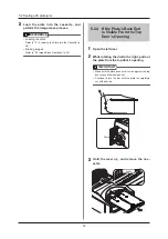
Страница 56: ...lever up and remove the cas sette IMPORTANT There is a chance that the plate is still inside of the cassette be careful to pull out the cassette very slowly so as not to scratch the plate Lever 2 Che...

Страница 57: ...oth 6 Remove the plate at the bottom from the rear door s opening IMPORTANT Make sure the plate does not hit or rub against the rear door or any other component 7 Push the guide back into place until...

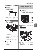
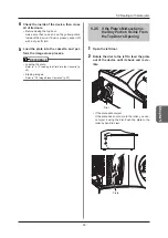
Страница 58: ...Erase Operation p 30 5 2 4 If the Plate s Back End is Visible From the Top Door s Opening 1 Open the left door 2 While rotating the dial to the right pull out the plate from the top door s opening IMP...

Страница 59: ...oller you can not eject it using the dial Push the plate to the roller by hand to eject Plate 4 Check the inside of the device then close all of its doors Before closing the top door make sure that no...

Страница 60: ...e device Dial 4 Hold the lever up and remove the cas sette Lever 5 Check the inside of the device then close all of its doors Before closing the top door make sure that no dust is on the yellow portio...

Страница 61: ...efore turning the power ON etc 1 Open the top door CAUTION Do not let foreign objects dust or debris get inside of the device Top Door 2 Hold the lever up and remove the cas sette Lever 3 Check the in...

Страница 62: ...62...

Страница 63: ...63 Chapter 6 Maintenance An explanation of maintenance items that must be followed for safe device operation...

Страница 64: ...Intake vent Exhaust outlet cleaning Once per month 6 2 3 Intake Vent Exhaust Outlet Cleaning p 65 Light collection unit cleaning keeping them dust free When a white line error occurs 6 2 4 Light Coll...

Страница 65: ...not come off wipe it with a slightly damp cloth then wipe it dry with a dry cloth 6 2 3 Intake Vent Exhaust Outlet Cleaning Cleaning methods 1 Use a vacuum to remove dust from the in take vent and ex...

Страница 66: ...Use the included cleaning tool to clean the feeding roller Be sure to clean the feeding roller when messages such as Roller cleaning required are displayed on the image processing controller CAUTION...

Страница 67: ...CAUTION Do not wipe the adhesive sheet with a cloth paper or the like There is a risk that fibers or dust may adhere to the adhesive sheet To dry the adhesive sheet expose it to the air and dry it nat...

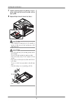
Страница 68: ...slot take care not to get your fingers or other things caught in it CAUTION Do not leave the back of the cleaning tool exposed to direct sunlight There is a risk that the adhesive sheet may soften Sto...

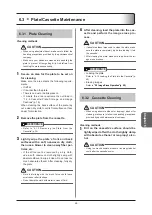
Страница 69: ...If the dirt cannot be removed by a dry cloth use a soft nonwoven cloth slightly damp with absolute ethanol to wipe it clean Do not use too much absolute ethanol After cleaning fully dry the plate CAUT...

Страница 70: ...70...

Страница 71: ...71 Appendix A list of device specifications etc...

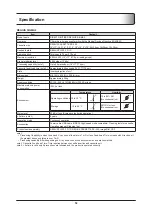
Страница 72: ...ess Environment Temperature Humidity Operating conditions 10 to 30 C 15 to 80 RH No condensation 15 RH 80 RH Storage 10 to 40 C 90 RH or less No condensation 0 RH 90 RH Noise level 53 dB or less Avera...

Страница 73: ...ving the cassette 61 I image erase mode 30 image erasing 26 30 image reading 26 32 installation 17 intake vent 23 65 J jamming 54 JM 8 L Light Collection Unit 26 65 Light Collection Unit Cleaning Hand...

Страница 74: ...74...

Страница 75: ......

Страница 76: ...A5ERBA01EN05 2015 08 31 JD...

Отзывы: