2 - G - 2
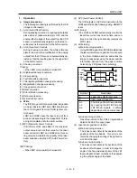
DEVELOPING UNIT
PRCB
24VDC
5VDC
SGND
B CONT
B SHIFT
B FB
5VDC
SGND
24VDC
24VDC
PGND
DCPS1
DCPS2
HV1
MS2 MS1
BIAS
PRCB
DCPS2
M3
24VDC
PGND
M3 CONT
M3 CLK
M3 EM
MS2
MS1
[3] M3 (Developing Unit Drive) Control
M3 (developing) is controlled by the PRCB (printer
control board) and the motor drive power is supplied
by DCPS2 (DC power supply unit 2). When the front
left or right door of this machine opens or closes, MS1
(interlock 1) or MS2 (interlock 2) operates to interrupt
the DC power supply to M3, stopping the voltage
supply to the developing sleeve.
1.
Operation
M3 which is the 24V driven DC motor drives the
developing sleeve and agitator. M3 equipped with
speed control circuit send the rotation error signal
to PRCB when PLL lock is released longer than
the specified time period. M3 starts after the
specified time interval from the start switch is ON,
and stops after the specified time interval from
the charging wire unit stops charging.
2.
Signals
a.
Input signals
(1) M3 EM (M3 to PRCB)
M3 fault detection signal.
[H]: Abnormal rotation (when PLL is unlocked
for more than 1.5 seconds)
[L]: Normal rotation
b.
Output signals
(1) M3 CONT (PRCB to M3)
M3 drive control signal.
[H]: M3 ON
[L]: M3 OFF
[4] Developing Bias Control
The developing bias is controlled by PRCB (printer
control board) via the HV1(high voltage unit 1). When
the front left or right door of this machine opens or
closes, MS1 (interlock 1) or MS2 (interlock 2) operates
to interrupt the DC power supply to HV1, stopping the
voltage supply to the developing sleeve.
1.
Operation
The developing bias voltage is applied to the
developing sleeve based on the M2 (drum) rota-
tion state signal.
2.
Signals
a.
Input signals
(1) B FB (HV1 to PRCB)
Developing bias voltage feedback signal.
This signal monitors the developing bias voltage.
It is an 0V to 5V analog signal corresponding to
the output level.
b.
Output signals
(1) B CONT (PRCB to HV1)
Developing bias output ON/OFF control signal.
[L]: Developing bias ON
[H]: Developing bias OFF
(2) B SHIFT (PRCB to HV1)
Developing bias output level control signal.
The developing bias output level is controlled
according to the duty ratio of the pulse (PWM)
signal sent from the PRCB.
B SHIFT duty
20% to 80%
Developing bias output range -300 V to-800 V
Содержание 7075/FORCE 75
Страница 1: ...FEBRUARY 2003 CSM 7075 F75 7085 F85 SERVICE MANUAL MODELS 7075 FORCE 75 7085 FORCE 85...
Страница 2: ......
Страница 3: ...7075 FORCE 75 7085 FORCE 85 SERVICE MANUAL FEBRUARY 2003...
Страница 39: ...OUTLINE 1...
Страница 40: ...Blank page...
Страница 55: ...1 15 MAIN BODY 11 Paper Exit Drive Section FRONT Paper exit roller Paper exit motor M10...
Страница 56: ...1 16 MAIN BODY 12 Toner Supply Drive Toner supply motor 1 M11 FRONT Toner supply motor 2 M15 Toner cartridge...
Страница 58: ...1 18 MAIN BODY 14 Web Drive Section FRONT Web drive motor M16 Cleaning web...
Страница 59: ...UNIT EXPLANATION 2...
Страница 60: ...Blank page...
Страница 62: ...2 A 2 EXTERNAL SECTION Blank page...
Страница 120: ...2 K 6 TRAY 3 PAPER FEED UNIT Blank page...
Страница 126: ...2 L 6 BY PASS TRAY Blank page...
Страница 130: ...2 M 4 VERTICAL PAPER CONVEYANCE SECTION Blank page...
Страница 154: ...2 O 8 FIXING UNIT Blank page...
Страница 165: ...DISASSEMBLY ASSEMBLY 3...
Страница 216: ...3 H 4 TONER SUPPLY UNIT Blank page...
Страница 224: ...3 I 8 CLEANING TONER RECYCLE UNIT Blank page...
Страница 232: ...3 J 8 PAPER FEED UNITS OF TRAYS 1 AND 2 Blank page...
Страница 240: ...3 K 8 TRAY 3 PAPER FEED UNIT Blank page...
Страница 292: ...3 O 18 FIXING UNIT Blank page 3 O 16...
Страница 293: ...MODELS 7075 FORCE 75 7085 FORCE 85 SERVICE SECTION FEBRUARY 2003...
Страница 294: ......
Страница 315: ...ADJUSTMENT 1...
Страница 316: ......
Страница 343: ...1 19 25 ADJUSTMENT Blank page 1 19 2...
Страница 372: ...1 44 25 ADJUSTMENT 1 ADJUSTMENT Blank page...
Страница 458: ...1 114 OTHER ADJUSTMENT Blank page 1 112 2...
Страница 497: ...ISW 2...
Страница 498: ......
Страница 511: ...SERVICE 3...
Страница 512: ......
Страница 514: ...Blank page...
Страница 550: ...3 18 SERVICE Blank page...
Страница 551: ...ELECTRICAL PARTS LIST WIRING DIAGRAMS 4...
Страница 552: ......
Страница 610: ...4 40 Blank page METHOD ADDITION MODEL 7075 7085 MANUAL SERVICE HANDBOOK REVISED EDITION 3 DATE Jan 2002 PAGE 4 34 6...
Страница 611: ...JAM ERROR CODE LIST 5...
Страница 612: ......
Страница 625: ...5 13 JAM CODE LIST Blank page 5 11 2...
Страница 659: ...TIMING CHARTS 6...
Страница 660: ......
Страница 678: ...6 18 TIMING CHARTS Blank page...
Страница 679: ...INSTALLATION INSTRUCTIONS 7...
Страница 680: ......
Страница 692: ...Blank page...
Страница 704: ...Blank page...
Страница 724: ...Blank page...
Страница 730: ...Blank page...
Страница 736: ...Blank page...
Страница 758: ...Blank page...
Страница 780: ...Blank page...
Страница 832: ...Blank page...
Страница 833: ...APPENDIX 7085 OVERALL WIRING DIAGRAM...
Страница 834: ......


