E-8
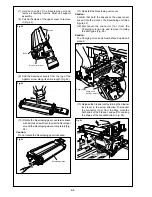
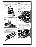
Caution:
Hold the Blade unlock arm pushing up.
e
Release the Blade unlock arm.
Caution:
Hold the Blade charge lever at the full rotated
position.
r
Release the Blade charge lever.
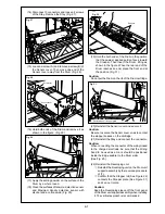
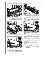
(23) Check the warp of the Toner leakage preven-
tive guide sheet of the Cleaner unit (Fig. 33).
Caution:
Toner leakage may be brought about, If the guide
sheet at the both ends of Cleaner unit is warped
slightly toward the Toner guide brush. If so, modify
that portions of the guide sheet by referencing the
procedure
q
.
q
Modify the warp of the Toner leakage pre-
ventive guide sheet to make parallel with
the Toner guide brush, or to warp slightly
(less than 1mm) off the Toner guide brush.
(24) Reinstall the Cleaner unit and connect the
connector.
(25) Return the Drum unit support assembly to the
original position.
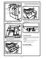
(26) Install the Coupling on the Drum shaft, with
the keyway of the Drum shaft meeting the
engraving (A) on the Coupling. Then insert a
plus screwdriver in the cross recess in the
Coupling and rotate it clockwise one rotation
or more until the notch on the Coupling (B) is
flush with the level of the Drum bearing (C)
(Fig. 34).
Caution:
To prevent blurry copy that result from setting
powder attaching the Charging corona or the
developing lid scatter prevention sheet, remove
the Charging corona and developing unit and turn
the drum once or more.
(27) Withdraw the Drum unit support assembly.
(28) Reinstall the Developing unit.
q
Reinstall the Developing unit on the Drum
unit support assembly by the reversed pro-
cedure of (7).
w
Confirm that the Stopper roll (See Figure
22) contacts the Stopper plate (See Figure
31) and can not rotate.
Caution:
Keep the Developing sleeve off the front panel of
the Drum unit support assembly when installing it.
The vertical approach is recommended.
(29) Reinstall the Developer suction box.
(30) Reinstall the Charging corona unit and con-
nect the connector.
(31) Return the Drum unit support assembly to the
original position and secure it with 2 screws.
Blade unlock arm
Blade charge lever
Fig. 32
Toner guide brush
Toner leakage preventive
guide sheet
Fig. 33
Drum bearing (C)
Engraving (A)
Coupling
Notch (B)
Drum bearing (C)
Notch (B)
Fig. 34
Содержание 7075/FORCE 75
Страница 1: ...FEBRUARY 2003 CSM 7075 F75 7085 F85 SERVICE MANUAL MODELS 7075 FORCE 75 7085 FORCE 85...
Страница 2: ......
Страница 3: ...7075 FORCE 75 7085 FORCE 85 SERVICE MANUAL FEBRUARY 2003...
Страница 39: ...OUTLINE 1...
Страница 40: ...Blank page...
Страница 55: ...1 15 MAIN BODY 11 Paper Exit Drive Section FRONT Paper exit roller Paper exit motor M10...
Страница 56: ...1 16 MAIN BODY 12 Toner Supply Drive Toner supply motor 1 M11 FRONT Toner supply motor 2 M15 Toner cartridge...
Страница 58: ...1 18 MAIN BODY 14 Web Drive Section FRONT Web drive motor M16 Cleaning web...
Страница 59: ...UNIT EXPLANATION 2...
Страница 60: ...Blank page...
Страница 62: ...2 A 2 EXTERNAL SECTION Blank page...
Страница 120: ...2 K 6 TRAY 3 PAPER FEED UNIT Blank page...
Страница 126: ...2 L 6 BY PASS TRAY Blank page...
Страница 130: ...2 M 4 VERTICAL PAPER CONVEYANCE SECTION Blank page...
Страница 154: ...2 O 8 FIXING UNIT Blank page...
Страница 165: ...DISASSEMBLY ASSEMBLY 3...
Страница 216: ...3 H 4 TONER SUPPLY UNIT Blank page...
Страница 224: ...3 I 8 CLEANING TONER RECYCLE UNIT Blank page...
Страница 232: ...3 J 8 PAPER FEED UNITS OF TRAYS 1 AND 2 Blank page...
Страница 240: ...3 K 8 TRAY 3 PAPER FEED UNIT Blank page...
Страница 292: ...3 O 18 FIXING UNIT Blank page 3 O 16...
Страница 293: ...MODELS 7075 FORCE 75 7085 FORCE 85 SERVICE SECTION FEBRUARY 2003...
Страница 294: ......
Страница 315: ...ADJUSTMENT 1...
Страница 316: ......
Страница 343: ...1 19 25 ADJUSTMENT Blank page 1 19 2...
Страница 372: ...1 44 25 ADJUSTMENT 1 ADJUSTMENT Blank page...
Страница 458: ...1 114 OTHER ADJUSTMENT Blank page 1 112 2...
Страница 497: ...ISW 2...
Страница 498: ......
Страница 511: ...SERVICE 3...
Страница 512: ......
Страница 514: ...Blank page...
Страница 550: ...3 18 SERVICE Blank page...
Страница 551: ...ELECTRICAL PARTS LIST WIRING DIAGRAMS 4...
Страница 552: ......
Страница 610: ...4 40 Blank page METHOD ADDITION MODEL 7075 7085 MANUAL SERVICE HANDBOOK REVISED EDITION 3 DATE Jan 2002 PAGE 4 34 6...
Страница 611: ...JAM ERROR CODE LIST 5...
Страница 612: ......
Страница 625: ...5 13 JAM CODE LIST Blank page 5 11 2...
Страница 659: ...TIMING CHARTS 6...
Страница 660: ......
Страница 678: ...6 18 TIMING CHARTS Blank page...
Страница 679: ...INSTALLATION INSTRUCTIONS 7...
Страница 680: ......
Страница 692: ...Blank page...
Страница 704: ...Blank page...
Страница 724: ...Blank page...
Страница 730: ...Blank page...
Страница 736: ...Blank page...
Страница 758: ...Blank page...
Страница 780: ...Blank page...
Страница 832: ...Blank page...
Страница 833: ...APPENDIX 7085 OVERALL WIRING DIAGRAM...
Страница 834: ......

